INGERSOLL RAND COMPANY LTD
209 NORTH MAIN STREET – BRYAN, OHIO 43506
(800) 495-0276
FAX (800) 892-6276
© 2012 CCN 15331416
OPERATOR’S MANUAL AF1260-XX
READ THIS MANUAL CAREFULLY BEFORE INSTALLING,
OPERATING OR SERVICING THIS EQUIPMENT.
It is the responsibility of the employer to place this information in the hands of the operator. Keep for future reference.
12” AIR MOTORS
6” STROKE
Also covers 637489 service kits
INCLUDING: SERVICE KITS, TROUBLESHOOTING, PARTS LIST,
DISASSEMBLY & REASSEMBLY.
SERVICE KITS
Use only genuine ARO® replacement parts to assure com-
patible pressure rating and longest service life.
637489 for general repair of all air motors.
GENERAL DESCRIPTION
DO NOT EXCEED MAXIMUM OPERATING
PRESSURE AS INDICATED ON PUMP MODEL PLATE.
REFER TO GENERAL INFORMATION SHEET
FOR ADDITIONAL SAFETY PRECAUTIONS AND IMPOR-
TANT INFORMATION.
This manual only covers the air motor section. It is one of
four documents which support an ARO pump. Replace-
ment copies of these forms are available upon request.
Pump Model Operator’s Manual.
General Information for Air Operated or Hydraulically
Operated Pumps.
Lower Pump End Operator’s Manual.
Air or Hydraulic Motor Operator’s Manual.
The 12” air motor is a general purpose power unit and
is used with many 2-ball and chop check pumps. It uti-
lizes tie rod type construction for easy breakdown and it
connects to the various lower ends via tie rods for easy
operation. Consult pump model operator’s manual for
specic instructions.
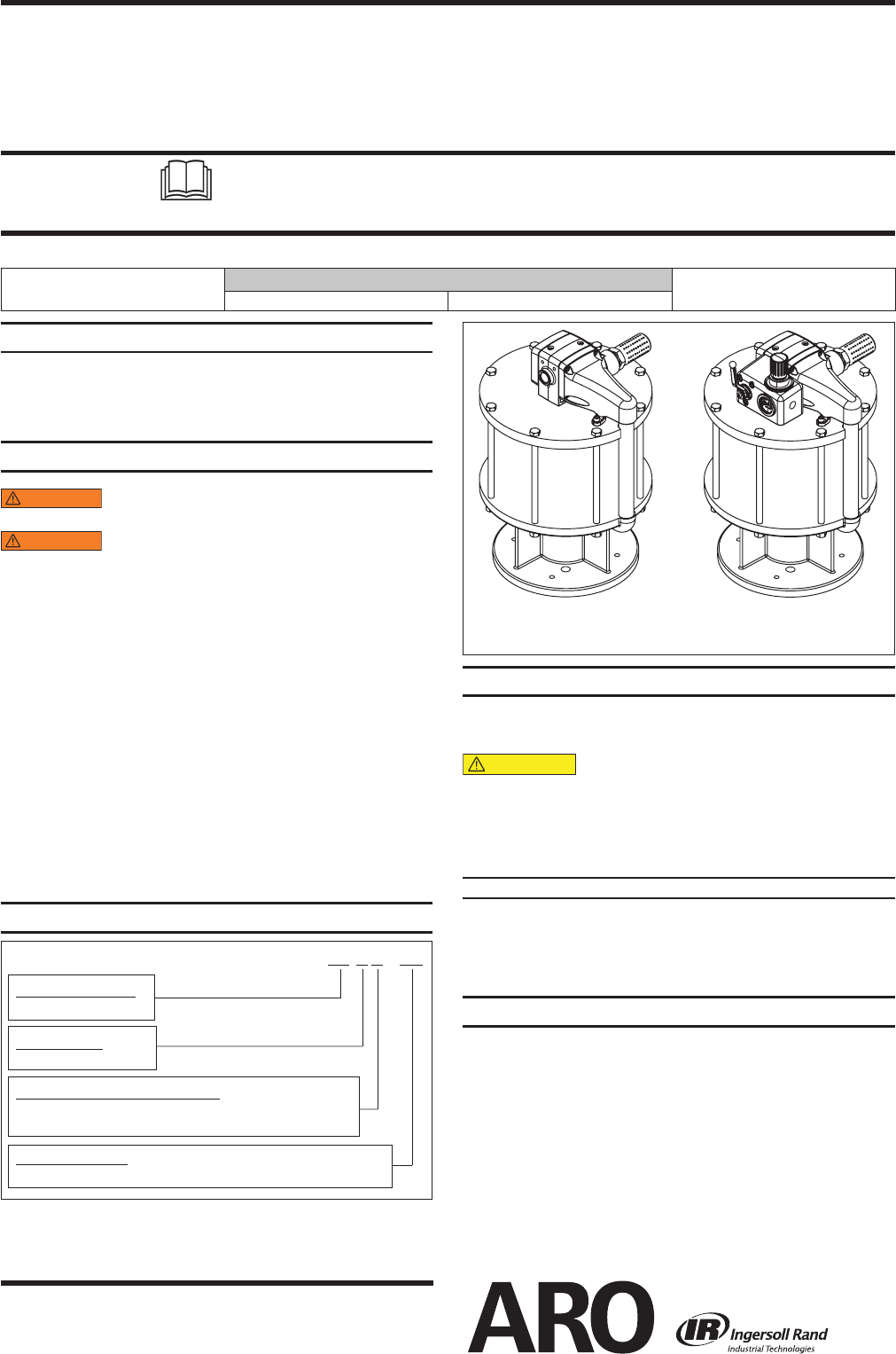
THIS MANUAL COVERS THE FOLLOWING MODELS
MODEL
AF1260 AF1260-01
Figure 1
OPERATING AND SAFETY PRECAUTIONS
DO NOT EXCEED MAXIMUM AIR INLET PRESSURE OF
90 P.S.I. (6.2 BAR) OR 75 CYCLES PER MINUTE.
High pressure equipment – Always dis-
connect air supply and relieve material pressure be-
fore attempting to service.
A ground lug is located on the air motor. This ground
lug allows proper grounding of the pump.
MATERIAL CODE
[A] = Aluminum [D] = Acetal
[B] = Buna Nitrile [PP] = Polypropylene
[Br] = Brass [SS] = Stainless Steel
[Bz] = Bronze [Ef] = Epoxy - Fiberglass Filament Reinforced
[C] = Carbon Steel [CK] = Ceramic
MODEL DESCRIPTION CHART
A F 12 X X – XX
Air Motor Diameter
12 - 12”
Air Motor Options
01 – Integrated On/O Valve and Regulator
Air Motor Base/Rod Combination
0 - Divorced pump base with quick coupled rod connection
(See Figure 3)
Stroke Length
6 - 6”
DISASSEMBLY OF AIR MOTOR
NOTE: All threads are right hand.
Force the piston assembly up by pushing the (115) rod
toward the top of the air motor.
Remove the (201) muffler/muffler assembly for ease of
disassembly.
Remove the four (138) socket head screws from the (140)
head manifold and the one (138) socket head screw form the
(122) head plate. Remove the (140) head manifold by pull-
ing up and outward to remove from tubes (114) and (137).
Remove (141) major gasket from the (140) head mani
fold.
1.
2.
3.
4.
(continued on page 3)
RELEASED:
REVISED:
8-16-10
8-10-12
(REV. 02)


