


AF1260-XX (en) Page 3 of 4
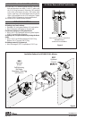
Remove tubes (114) and (137) by pulling upward.
Remove the four (113) O-rings from both tubes (114) and
(137).
Remove the (142) valve plate and the (143) D-valve from
the (144) valve housing.
Remove the four (138) socket head screws to extract the
(150) pilot cover.
Remove the (148) pilot gasket from the (150) pilot cover.
Remove the (147) pilot valve plate and the (146) pilot
insert from the (144) valve housing.
Remove the two (145) socket head screws from the (144)
valve housing.
Remove the (144) valve housing by pulling straight up.
Remove the (124) O-ring, the (135) vent bushing, and the
(136) U-cup from the (144) valve housing.
Remove the (128) O-ring and the (126) sleeve from the
motor assembly by sliding it straight up.
Pull the (134) spool as far from the motor assembly as
possible to expose the under side of the spool itself.
Locate and remove the (129) snap ring from the (134)
spool utilizing snap ring pliers.
Lift to remove the (134) spool and remove the (133)
U-cup from it.
Slide the (131) pin to remove the (132) driver, (130) washer,
and (129) snap ring from the (120) trip rod assembly.
Remove the eight (109) nuts from (121) hex head bolts.
Remove the eight (121) bolts from the (122) head plate
and the (101) base assembly.
Remove (122) head plate from the (112) air cylinder.
Remove the (111) O-ring, the (125) cap, and (123) O-ring
from the (122) head plate.
Pull upward on (112) air cylinder until (203) piston as-
sembly separates from the (101) base assembly. If, in this
step, the (203) piston assembly is not pulled from the
(101) base assembly, then remove it after removing the
(112) air cylinder.
If the (112) air cylinder and (203) piston assembly are
removed as one unit, then remove the (203) piston as-
sembly from the (112) air cylinder.
Remove the (116) O-ring from the (117) piston.
Remove the (111) O-ring from (101) base assembly.
Remove (154) snap ring, (153) washer, and (152) U-cup
from the (101) base assembly.
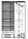
REASSEMBLY OF AIR MOTOR
Apply grease to all O-rings, U-cups, and other rubber
goods before installing.
Install (152) U-cup, (153) washer, and (154) snap ring into
the (101) base assembly.
Install the (111) O-ring in the groove on the (101) base
assembly.
Install the (116) O-ring in the groove on the (117) piston.
Push (115) piston rod thru the (101) base assembly, be-
ing careful not to damage the lips of the (152) U-cup or
the (102) O-ring.
Lubricate the inside diameter of the (112) air cylinder and
slide it down over the (203) piston assembly and onto the
(101) air motor base assembly.
Align notch in (122) head plate with the port in (101) base
assembly and press the (122) head plate down until it is
seated against the (112) air cylinder. The (120) trip rod as-
sembly must lead thru the center of the (122) head plate.
5.
6.
7.
8.
9.
10.
11.
12.
13.
14.
15.
16.
17.
18.
19.
20.
21.
22.
23.
24.
25.
26.
27.
1.
2.
3.
4.
5.
6.
7.
Assemble the eight (121) bolts thru the (122) head plate
and the (101) base assembly.
Assemble the eight (109) nuts to (121) hex head bolts
and tighten per specied torque sequence and value.
Pull the (120) trip rod assembly as far out of the air mo-
tor assembly as possible, slide the (123) O-ring over the
(120) trip rod assembly and down into the gland found
in the (122) head plate.
Slide the (125) cap over the (120) trip rod assembly and
down into the bore found in the (122) head plate.
Slide the (129) snap ring rst and the (130) washer sec-
ondly, onto the (120) trip rod assembly.
Slide the (132) driver onto the (120) trip rod assembly.
Align the hole of the (132) driver with the hole in the
(120) trip rod assembly and insert the (131) pin.
Assemble the (133) U-cup to the (134) spool. Take note
of the (133) U-cup lips should point down towards the
(122) head plate.
Slide the (134) spool onto the (120) trip rod assembly over
the (132) driver and insert the (130) washer behind it. Uti-
lizing snap ring pliers, assemble the (129) snap ring to the
internal groove found in the (134) spool. Be certain that
the (129) snap ring is fully engaged into the groove. Slide
the (134) spool downward into the bore of the (122) head
plate nesting on top of the (125) cap.
Lubricate the inside diameter of the (126) sleeve and
slide it onto the (134) spool and locating it into the (125)
cap.
Install the (128) O-ring onto the top gland of the (126)
sleeve.
Install the (136) U-cup, the (135) vent bushing into the
center bottom bore of the (144) valve housing. Take note
that the (136) U-cup lips must be facing up towards the
top of the (144) valve housing. Install the (124) O-ring
into the bottom recess gland of the (144) valve housing.
Install the (144) valve housing to the motor assembly
by sliding the center bore onto the (134) spool and the
(126) sleeve. Take caution not to dislodge any of the
O-rings (124 & 128). Take note to align the large valve
pocket on the side of the (144) valve housing towards
the notch in the (122) head plate.
Install the two (145) socket head screws thru the (144)
valve housing and thread into the (122) head plate. The
(144) valve housing may need to be rotated slightly to
align the tapped holes. Tighten the (145) socket head
screws per specied torque value.
Install the (146) pilot insert thru the (144) valve housing
and into the (134) spool. The (134) spool may need to
be turned to orient its’ shallower slot to face the smaller
pocket of the (144) valve housing.
Install the (147) pilot valve plate into the (144) valve
housing covering the (146) pilot insert.
Install the (148) pilot gasket into the (150) pilot cover
and assemble to the (144) valve block using four (138)
socket head screws. Tighten to torque specications.
Install the (143) D-valve thru the (144) valve housing and
into the (134) spool.
Install the (142) major valve plate into the (144) valve
housing covering the (143) D-valve.
Install the four (113) O-rings onto both (114 & 137) tubes.
Loosely install the (137) tube into the bore in the (122)
head plate.
Loosely install the (114) tube into the bore in the (101)
base assembly.
8.
9.
10.
11.
12.
13.
14.
15.
16.
17.
18.
19.
20.
21.
22.
23.
24.
25.
26.
27.
28.
(continued on page 4)
DISASSEMBLY OF AIR MOTOR (CONT’D)