


Page 4 of 4 LM2250E-XX-B3 (en)
PN 97999-1343
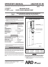
PUMP DISASSEMBLY
NOTE: All threads are right hand. Refer to gure 2 (page 3). Discon-
nect air supply and relieve all system pressure prior to servicing.
Carefully remove the parts, inspect for damage, nicks or excessive
wear and determine if any parts will need replacement.
Using a 7/8” wrench, unthread and remove (11) adapter, con-
taining (12 and 13) “O” rings, releasing (14) mu er housing.
Using a 7/16” wrench, remove (28) nuts.
Remove four (1) bolts, (2) upper cap and (3) gasket.
Remove (10) cylinder, containing (4) sleeves and (7) spools.
Using (1) bolt, push (7) spools and (4) sleeves out “sleeve” end
of (10) cylinder.
Remove (16) retaining ring, (17) washer and (19) piston.
Remove (22) dowel pin, releasing (20) piston adapter.
Remove (3) gasket.
Clamp (31) extension tube horizontally in a vise. Unthread
and remove (27) base, (30) gasket, (26) spring and (25) washer.
NOTE: Remove (24) rod seal only if replacement is necessary.
Pull up on (33) piston rod to reveal (35) cotter pin.
Remove (35) cotter pin and (34) connecting pin, releasing (33)
piston rod.
Remove (54) internal circlip from (52) primer tube by using
circlip pliers and take out the (53) grease lter.
Using (33) piston rod, push down on (36) connector until it
bottoms.
Remove (51) retainer ring.
Push (50) primer up into (52) primer tube.
Lightly wedge a flat blade screwdriver between (50) primer
and (52) primer tube, so (50) primer unthreads with (52) prim-
er tube.
Insert a 5/16” diameter rod thru the cross holes in (52) primer
tube and use the rod to unthread and remove (52) primer
tube.
Remove (42) spacer, (47) gasket and (48) valve seat from (52)
primer tube.
Remove (43 - 46) foot valve assembly from (49) primer rod.
Remove (43) retaining ring, releasing (44) “U” cup. NOTE: Do
not remove (45) guide unless replacement is necessary.
Remove (41) guide washer.
Clamp (37) lower suction tube horizontally in a vise. Unthread
and remove (31) extension tube and (32) gasket.
Using a 7/32” diameter rod in the cross hole in (36) connector
and a 9/16” wrench on the ats of (38) plunger, unthread and
remove (36) connector from (38) plunger. NOTE: Do not dam-
age the o.d. of (38) plunger in any way.
Using a 5/32” diameter rod in the cross hole of (49) primer rod
and a 9/16” wrench on ats of (38) plunger, unthread and re-
move (49) primer rod, releasing (40) ball and (39) ball stop.
PUMP REASSEMBLY
NOTE: Thoroughly clean and lubricate all seals and bores with Shell
Gadus S2 U1000
upon assembly. Replace all soft parts with
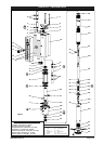
new ones included in the repair kit. Note: Refer to the illustration
( gure 2, page 3) for “U” cup lip seal direction.
Assemble (39) ball stop and (40) ball into (38) plunger, secur-
ing with (49) primer rod. NOTE: Torque (49) primer rod to 70 -
100 in. lbs (7.9 - 11.3 Nm).
Thread (36) connector to (38) plunger, using a 7/32” diameter
rod thru the cross hole to tighten. NOTE: Tighten (36) connec-
tor to 17 - 25 ft lbs (23.1 - 33.9 Nm).
Assemble (45) guide and (44) “U” cup into (46) valve body,
securing with (43) retaining ring. NOTE: Assemble chamfered
corner of (45) guide into (46) valve body rst.
1.
2.
3.
4.
5.
6.
7.
8.
9.
10.
11.
12.
13.
14.
15.
16.
17.
18.
19.
20.
21.
22.
23.
24.
1.
2.
3
.
Assemble (41) guide washer and (43 - 46) foot valve assembly
onto (49) primer rod.
Assemble (42) spacer, (47) gasket and (48) valve seat onto (49)
primer rod.
Thread (50) primer onto (49) primer rod, securing with (51)
retainer ring.
Thread (52) primer tube to (37) lower suction tube and tight-
en. NOTE: Torque (52) primer tube to 65 - 75 ft lbs (88.1 - 101.7
Nm).
Assemble (33) piston rod to (36) connector, securing with (34)
connecting pin and (35) cotter pin.
Assemble (32) gasket and (31) extension tube to (37) lower
suction tube and tighten. NOTE: Torque (31) extension tube to
65 - 75 ft lbs (88.1 - 101.7 Nm).
Assemble (23) “O” ring, (24) rod seal, (25) washer, (26) spring
and (30) gasket into (27) base and assemble (27) base to (31)
extension tube. Clamp (27) base horizontally in a vise and
tighten (31) extension tube. NOTE: Torque (31) extension tube
to 65 - 75 ft lbs (88.1 - 101.7 Nm).
Push up on (50) primer, exposing (33) piston rod.
Assemble (3) gasket to (27) base.
Assemble (21) “O” ring to (20) piston adapter and assemble (20)
piston adapter to (33) piston rod, securing with (22) dowel pin.
Replace (18) “U” cups on (19) piston and assemble (19) piston
onto (20) piston adapter, securing with (17) washer and (16)
retaining ring.
Replace (5) “O” rings on (4) sleeves and assemble (4) sleeves
into (10) cylinder. NOTE: Assemble each sleeve into the end of
the cylinder nearest the exhaust hole.
Replace (6 and 9) “O” rings and (8) “U” cups on (7) spools and
assemble (7) spools into (10) cylinder from the opposite end
as the (4) sleeve went in.
Assemble (10) cylinder onto the pump, being careful when
sliding over the lips of (18) “U” cups. NOTE: Be sure (3) gasket is
seated properly.
Replace (3) gasket on (2) upper cap and assemble (2) upper
cap to (10) cylinder.
Assemble (1) bolts to pump, securing with (28) nuts. NOTE:
Torque (28) nuts to 80 - 90 in. lbs (9.0 - 10.2 Nm).
Replace (12 and 13) “O” rings on (11) adapter.
Assemble (15) foam liners to (14) mu er housing.
Assemble (14) mu er housing to (10) cylinder, securing with
(11) adapter. NOTE: Torque (11) adapter to 70 - 80 in. lbs (7.9 -
9.0 Nm).
Assemble (53) grease lter to (52) primer tube, keeping open
and inside the (52) primer tube and place the (54) internal cir-
clip inside the groove of (52) primer tube.
TROUBLE SHOOTING
Pump problems can occur in either the air motor section or the
lower pump end section. Use these basic guidelines to help deter-
mine which section is affected. Be sure to eliminate any possible
non-pump problems before suspecting pump malfunction.
Pump will not cycle or will not deliver material.
Be certain to check for non-pump problems, including kinked,
restrictive or plugged inlet / outlet hose or dispensing device.
Depressurize the pump system and clean out any obstructions
in the inlet / outlet material lines.
Check all seals, including track gaskets.
Check direction of “U” cup lips.
Remove (54) circlip. Take out (53) grease filter and clean. Re-
install (53) grease filter inside (52) primer tube and retain by
installing (54) circlip.
4.
5.
6.
7.
8.
9.
10.
11.
12.
13.
14.
15.
16.
17.
18.
19.
20.
21.
22.
23.
y
y
y
y