


Disassembly Instruction:
If necessary, the unit may be removed from the panel and
opened.
Warning: Disconnect all ac power from the unit
before proceeding.
1. Make sure the AC power is disconnected.
2. Remove all wiring connections from the rear of the
meter. To remove power and input connectors bend the
side panel detents on the case outward to release the
connectors, then pull connectors from the meter.
3. To remove meter from the case, squeeze left and right
sides of the bezel to release, then pull from case.
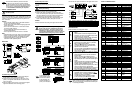
WIRING
Wire the instrument according to the figure shown below.
Warning: Do not connect ac power to your
device until you have completed all input and
output connections. This device must only be
installed by a specially trained electrician with
corresponding qualifications. Failure to follow all
instructions and warnings may result in injury!
This Quick Start Reference provides information
on setting up your instrument for basic operation.
The latest complete Communication and Operational
Manual as well as free Software and ActiveX Controls
are available at www.omega.com/specs/iseries or
on the CD-ROM enclosed with your shipment.
SAFETY CONSIDERATION
This device is marked with the international
Caution symbol.
The instrument is a panel mount device protected in
accordance with EN61010-1:2001. Remember that the unit
has no power-on switch. Building installation should include
a switch or circuit-breaker that must be compliant to IEC
947-1 and 947-3.
SAFETY:
• Do not exceed voltage rating on the label located on
the top of the instrument housing.
• Always disconnect power before changing signal and
power connections.
• Do not use this instrument on a work bench without
its case for safety reasons.
• Do not operate this instrument in flammable or
explosive atmospheres.
• Do not expose this instrument to rain or moisture.
EMC:
• Whenever EMC is an issue, always use shielded cables.
• Never run signal and power wires in the same conduit.
• Use signal wire connections with twisted-pair cables.
• Install Ferrite Bead(s) on signal wire close to the
instrument if EMC problems persist.
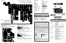
MOUNTING
Panel Mounting Instruction:
1. Using the dimensions from the panel cutout diagram
shown above, cut an opening in the panel.
2. Insert the unit into the opening from the front of the
panel, so the gasket seals between the bezel and the
front of the panel.
3. Slide the retainer over the rear of the case and tighten
against the backside of the mounting panel.
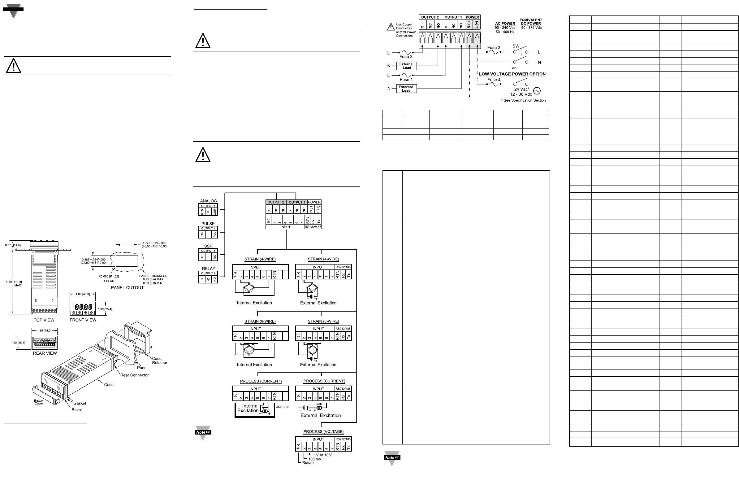
START HERE
Connect the main power connections in the figure shown below.
FUSE Connector Output Type For 115Vac For 230Vac DC
FUSE 1 Output 1 Relay 3 A(T) 3 A(T) -
FUSE 2 Output 2 Relay 3 A(T) 3 A(T) -
FUSE 3 Power N/A 100 mA(T) 100 mA(T) 100 mA(T)
FUSE 4 Power N/A N/A N/A 400 mA(T)
CONFIGURATION
Button Functions in Configuration Mode
• To enter the Menu, the user must first press
a
button.
• Use this button to advance/navigate to the next
menu item. The user can navigate through all the
top level menus by pressing
a
.
• While a parameter is being modified, press
a
to
escape without saving the parameter.
• Press the up
b
button to scroll through “flashing”
selections. When a numerical value is displayed
press this key to increase value of a parameter
that is currently being modified.
• Holding the
b
button down for approximately
3 seconds will speed up the rate at which the
setpoint value is incremented.
• In the Run Mode pressing
b
causes the display to
flash the PEAK or GROSS value – press again to
return to the Run Mode.
• Press the down
c
button to go back to a previous
Top Level Menu item.
• Press this button twice to reset the controller to
the Run Mode.
• When a numerical value is flashing (except
setpoint value) press
c
to scroll digits from left to
right allowing the user to select the desired digit to
modify.
• When a setpoint value is displayed press
c
to
decrease value of a setpoint that is currently being
modified. Holding the
c
button down for
approximately 3 seconds will speed up the rate at
which the setpoint value is decremented.
• In the Run Mode pressing
c
causes the display to
flash TARE value to tare your reading (zeroing).
• Press the enter
d
button to access the submenus
from a Top Level Menu item.
• Press
d
to store a submenu selection or after
entering a value — the display will flash a
STRD
message to confirm your selection.
• To reset flashing PEAK or GROSS press
d
.
• In the Run Mode, press
d
twice to enable
Standby Mode with flashing
STBY
.
81765432
a
d
c
b
PK/GRS
(UP)
MENU
TARE
(DOWN)
ENTER
Reset: Except for Alarms, modifying any settings of
the menu configuration will reset the controller prior
to resuming Run Mode.
DISPLAY ABBREVIATIONS
SP1 Set Point 1 Value SP2 Set Point 2 Value
CNFG Configuration Menu INPt Input Type (Range)
INPt Input Type (range) 0 - 0.1 100 mV Input Voltage
0 - 1.0 1 V Input Voltage 0 - 10 10 V Input Voltage
0 - 20 20 mA Input Current
Rtio Ratiometric Operation RESO Display Resolution
bUtN Button Peak/Gross PEAk Peak Value
GROS Gross Value
RdG Reading Configuration
dEC Decimal Point F.FFF Decimal Point
..FFFF Position
LOAd Input Load EnbL Scaling with Known
Loads (Actual Value)
DSbL Scaling without Known L.PNt
Linearization Points
Loads (Calculated Value)
0002...
Number of Linearization
FLtR Filter Constant
...0010
Points
0001.. Filter Constant Value IN.Rd
Input/Reading Scale
..0128 and Offset Menu
IN 1 Input 1 Rd 1 Reading 1
IN 2 Input 2 Rd 2 Reading 2
ANLG Analog Output CURR Current Output
VoLt Voltage Output Rd 1 Reading 1
Out.1 Output 1 Rd 2 Reading 2
Out.2 Output 2
ALR1 Alarm 1 Menu AbSo Absolute Mode
_dEV Deviation Mode LtcH Latched Mode
UNLt Unlatched Mode Ct.CL Contact Closure
N.o. Normally Open N.c. Normally Closed
ActV Active Type AboV Active Above
bELo Active Below Hi.Lo Above High/Below
Low
bANd Above or Below Band A.P.oN
Alarm
Enable/Disable
at Power On
ALR.L Alarm Low Value ALR.H Alarm High Value
ALR.2 Alarm 2 Menu
LOOP Loop Break Menu b.tIM Loop Break Time
R.AdJ Reading Adjust SP.dN Set Point Deviation
OUt1 Output 1 Menu SELF Manual Control
º
ºLO Percent Low
º
ºHI Percent High
CtRL Control Type ON.OF On/Off Control
4 -20 Amplitude Control PId PID Control
ActN Action Type RVRS Reverse Action
dRct Direct Action ANt1 Anti Integral
AUto Auto PID A.tUN Auto Tune PID
StRt Start Auto Tune PID PRoP Proportional Band
RESt Reset Setup RAtE Rate Setup
CYCL Cycle Time dPNG Damping Factor
dEAd Dead Band
OUt2 Output 2 Menu
RAMP Ramp Time SOAk Soak Time
Id ID Code Menu CH.Id Change ID Code
FULL Full ID SP.Id Set Point ID
COMM Communication Option* NONE Communication is
Not Installed
COLR Display Color Selection N.CLR
Normal Color Display
1.CLR Alarm 1 Color Display 2.CLR Alarm 2 Color
Display
REd Display Color is Red AMbR Display Color is
Amber
GRN Display Color is Green
dSbL Disable ENbL Enable
ERRO Error + OL Input (+) Overload
* For abbreviations of Communication Option see Communication Manual.
If instrument has the
communication option,
the internal excitation
is not available. Use
external excitation to
power your transducer.