TS Series Conveyors Technical Manual 7610-002-98-29
Issued: 02-15-2006 Revised: N/A
SECTION 1: SPECIFICATION INFORMATION
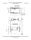
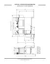
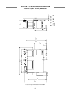
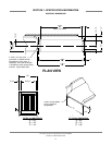
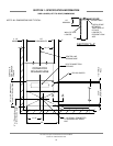
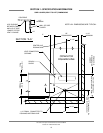
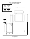
TS-66/TSC-66 (RIGHT TO LEFT) DIMENSIONS
10
LEGEND FOR TS-66/TSC-66 (RIGHT TO LEFT) DIMENSIONS:
A = Incoming electrical connection point, approximately 61-1/4” above the finished floor. Refer to machine data plate for elec-
trical requirements.
B = 1/2” IPS incoming water connection, approximately 61-1/4” above the finished floor. Electric heat models only.
C = 1/2” IPS prewash incoming water connection, approximately 61-1/4” above the finished floor. Electric heat models only.
D = 1-1/2” IPS drain point connection. If grease trap is required by code, size for 30 gallons per minute flowrate.
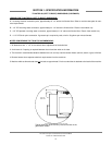
NOTES CONCERNING THE TS-66/TSC-66 DIMENSIONS:
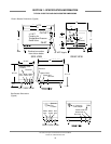
1. All dimensions are +/- 1/2” in the vertical due to adjustment of the bullet feet.
2. A minimum of 4” spacing is required between the unit and the walls on all sides.
3. The maximum recommended distance between the unit and any external booster heater (electric, steam or gas) is 20 feet.
4. Booster heaters have seperate electrical requirements from the machines.
5. Machine width as dimensioned does not
include an approximate 3” for the conduit that is attached to the back of the machine.
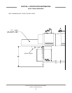
AUXILLARY
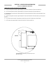
RINSE TANK
11-1/2"
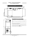
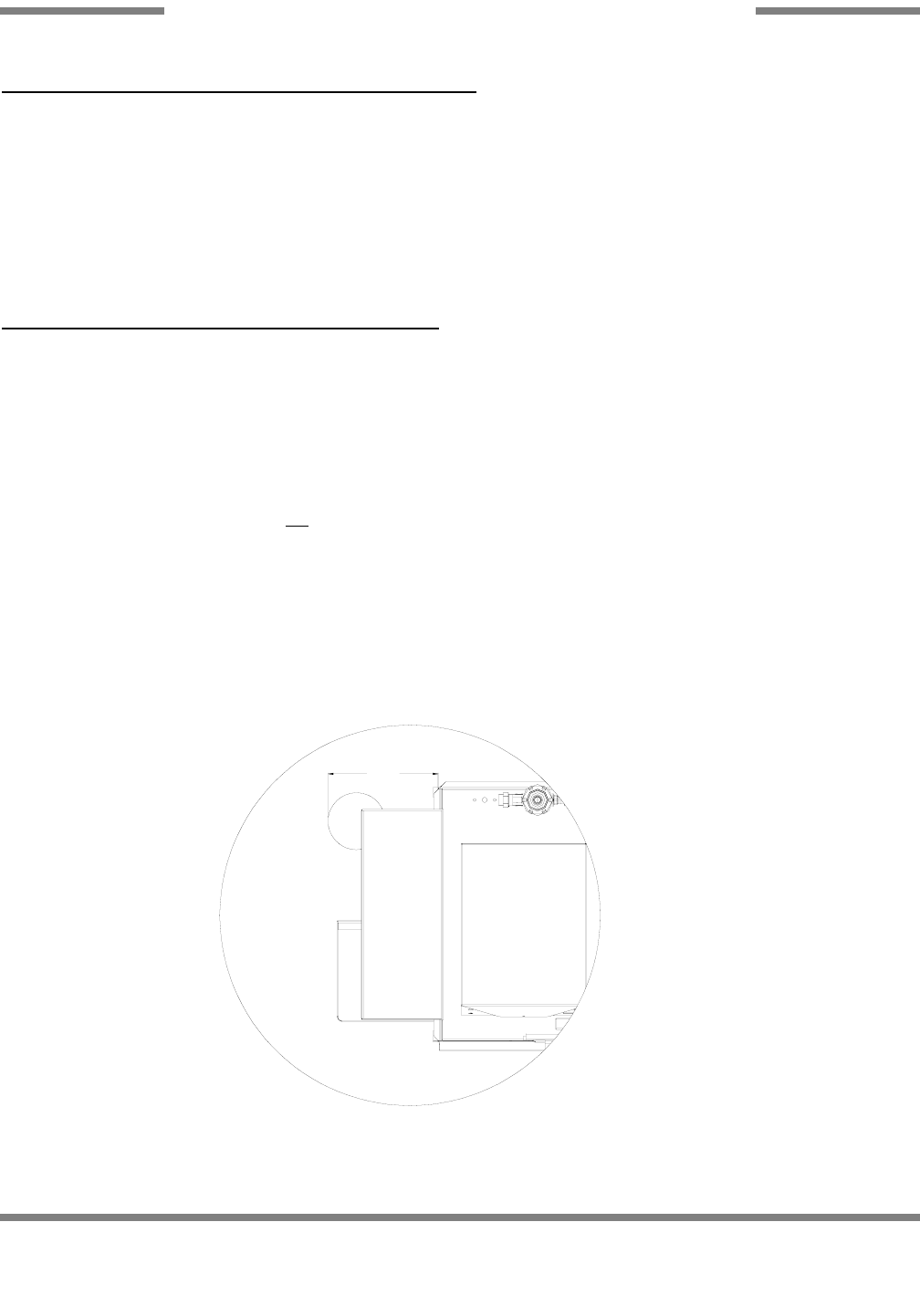
TYPICAL DIMENSION OF GAS MODEL AUXILLARY RINSE
TANK (SCALE 2:1)
Typical dimension of the auxillary rinse tank found on the
gas-heated models.


