


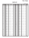
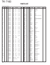
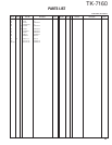
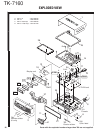
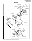

TK-7160
31
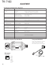
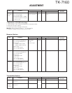
Receiver Section
1. Seisitivity 1) CH : RX low (Wide/Narrow) SSG ANT Check SINAD
CH : RX center (Wide/Narrow) Oscilloscope EXT. SP : 12dB or higher
CH : RX high (Wide/Narrow) AF V.M
2) SSG output Distortion meter
: –118dBm (0.28µV) (Wide)
: –116dBm (0.35µV) (Narrow)
Mod : 1kHz
Dev : ±3.0kHz (Wide)
Dev : ±1.5kHz (Narrow)
2. Squelch 9 1) CH : RX low (Wide) PC key Adjust to open the squelch
CH : RX center (Wide/Narrow)
CH : RX high (Wide)
2) SSG output
: 12dB SINAD+7dB
Mod : 1kHz
Dev : ±3.0kHz (Wide)
Dev : ±1.5kHz (Narrow)
3. Squelch 1 1) CH : RX low (Wide)
CH : RX center (Wide/Narrow)
CH : RX high (Wide)
2) SSG output
: 12dB SINAD+2dB
Mod : 1kHz
Dev : ±3.0kHz (Wide)
Dev : ±1.5kHz (Narrow)
Item Condition
Test equipment
Terminal
Parts Method
Specifications/
Remarks
Measurement
Adjustment
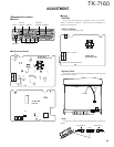
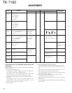
ADJUSTMENT
Transmitter Section
1. Frequency 1) CH : TX center Frequency counter ANT PC key Adjust to center frequency Within ±100Hz
2) Transmit
2. Maximum 1) CH : TX high Power meter VR1 28W ±1W
power 2) Transmit
limitting
Item Condition
Test equipment
Terminal
Parts Method
Specifications/
Remarks
Measurement
Adjustment
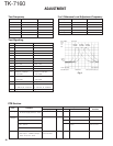
4. RF 1) CH : RX center (Wide) Tra generator ANT PC key Adjust the BPF waveform
bandpass CH : RX low (Wide) Spectrum analyzer BPF to Fig. 1
filter CH : RX high (Wide)
2) Tra generator output : –30dBm
Connect the spectrum analyzer
to BPF terminal
* Adjustment of TX VCO lock voltage
1. Remove R517, F501, R519 and R526 (all on component side).
2. Remove PCB from chassis.
3. Transmit and check voltage at [CV] point.
Warning : Do not transmit if step “1.” is not complete.
4. Adjust of voltage can be done by tuning TC442.
Item Condition
Test equipment
Terminal
Parts Method
Specifications/
Remarks
Measurement
Adjustment