


REPEATER OPERATION
Note:
Please consult your dealer for programming the repeater.
When power is applied to the unit, the POWER indicator
lights green.
Turn the VOLUME control clockwise until a click sounds,
to unmute the volume. Rotate to adjust the volume. Turn
the VOLUME control counterclockwise fully to mute the
volume.
The BUSY indicator lights green while receiving a signal,
and the TX indicator lights red while transmitting.
qq
qq
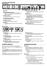
q Speaker
ww
ww
w REF (reference) indicator
Lights red when using an external reference
frequency. Lights green when using the internal
reference frequency.
ee
ee
e BUSY indicator
Lights green while a signal is being received.
rr
rr
r TX (transmit) indicator
Lights red while transmitting.
tt
tt
t POWER indicator
Lights green when power is applied.
yy
yy
y Display
Two, 7-segment digits display the channel number
or status.
uu
uu
u Programmable Function keys
Press these keys to activate their programmable
functions.
ii
ii
i TEST switch
Press to transmit an unmodulated signal with no
local microphone connected. If an external
modulation signal source is connected to the
CONTROL I/O jack, the RF signal is modulated
with this signal source.
oo
oo
o VOLUME control
Turn clockwise until a click sounds, to unmute the
volume. Rotate to adjust the volume. Turn
counterclockwise fully to mute the volume.
!0!0
!0!0
!0 MICROPHONE jack
Connect a microphone to this 8-pin modular jack.
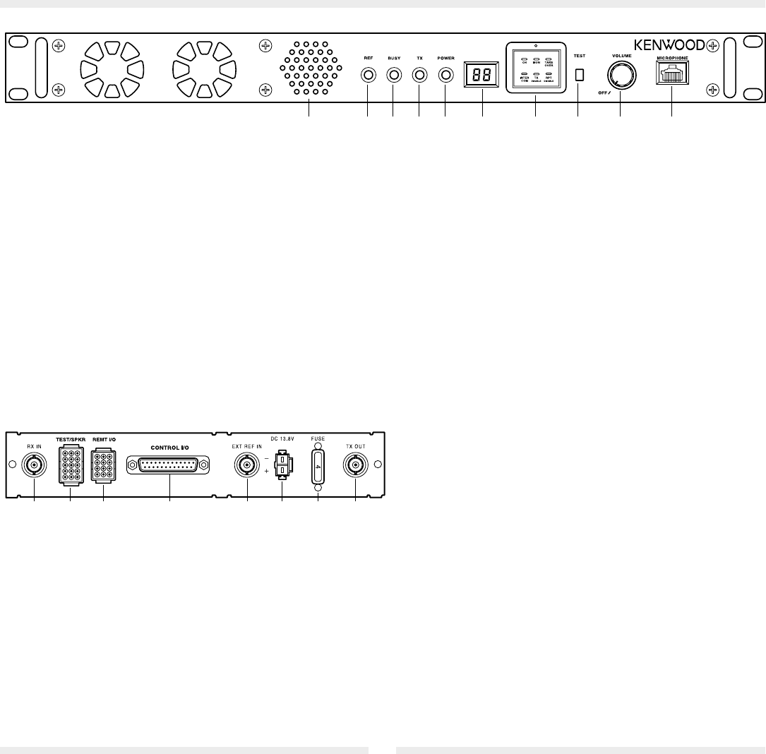
■ Rear Panel
qq
qq
q RX IN jack
Connect a RX antenna or a duplexer to this BNC
receptacle.
ww
ww
w TEST/SPKR jack
Test input/output jack. Connect an external
speaker to this jack.
ee
ee
e REMT I/O jack
Connect an external remote controller to this jack.
rr
rr
r CONTROL I/O jack
Connect an external programming device or
repeater controller to this DB-25 interface.
tt
tt
t EXT REF IN jack
Connect an external reference oscillator (10 MHz,
-10 dBm or higher) to this BNC receptacle.
yy
yy
y DC 13.8V jack
Connect a 13.8 V DC power supply to this jack.
uu
uu
u FUSE
Insert a 4 A blade fuse into this fuse holder.
ii
ii
i TX OUT jack
Connect a TX antenna or a duplexer to this BNC
receptacle.
TRANSCEIVER OPERATION
■ Receive
Adjust the volume to your desired level. You may
need to readjust the volume when you receive a
message from your dispatcher or another member in
your fleet.
• The BUSY indicator lights while a signal is being
received.
■ Transmit
1 Listen to the channel before transmitting, to make
sure it is not being used.
2 Press the microphone PTT switch and speak in
your normal speaking voice.
• FCC regulations require that you identify the
station you are calling as well as your own
station (your assigned call sign).
• The TX indicator lights while transmitting.
3 When you finish speaking, release the PTT switch.
CONTROLS AND FUNCTIONS
■ Front Panel
ww
ww
w
ee
ee
e
rr
rr
r
tt
tt
t
yy
yy
y
uu
uu
u
qq
qq
q
ii
ii
i
qq
qq
q
ww
ww
w
ee
ee
e
rr
rr
r
tt
tt
t
yy
yy
y
uu
uu
u
ii
ii
i
oo
oo
o
!0!0
!0!0
!0