ENGLISH
19
ASSEMBLING AND PREPARING
y
Unplug the power cord before moving or install-
ing the monitor to avoid electric shock.
y
Installing the monitor on the ceiling or on a
slanted wall may result in the monitor falling off,
which could lead to injury. Use an authorized LG
wall mount and contact the local dealer or quali-
fied personnel.
y
Applying excessive force when tightening
screws may cause damage to the monitor. Dam-
age caused in this way will not be covered by
the product warranty.
y
Use the wall mounting bracket and screws that
conform to VESA standards. Damage caused by
the use or misuse of inappropriate components
will not be covered by the product warranty.
y
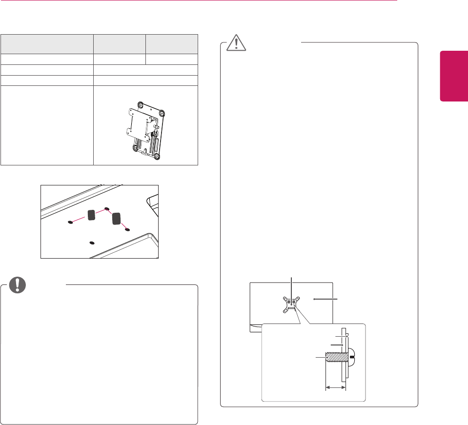
When measured from the back of the monitor,
the length of each installed screw must be 8 mm
or less.
Wall Mount Plate
Back of the Monitor
Screw
Dimensions
: M4 x L10
Wall Mount Plate
Back of the Monitor
Max 8 mm (0.3 inch)
CAUTION
Model 25UM65
25UM64
34UM65
34UM64
Wall Mount (A x B) 75 x 75 100 x 100
Stand Screw M4 x 10 mm
Required Screws 4
Wall Mount Plate
(Optional)
RW120
y
Wall Mount (A x B)
A
B
y
Use the screws specified by VESA standards.
y
The wall mount kit includes the installation guide
and all necessary parts.
y
The wall mounting bracket is optional. You can
obtain optional accessories from your local dealer.
y
The length of the screw may differ for each wall
mounting bracket. Be sure to use the proper
length.
y
For more information, please refer to the user
manual for the wall mounting bracket.
NOTE


