


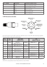

Pin / Socket Wire color Function (NMEA 2000)
1 Green Can-D, Drain wire, Shield
2 Red Can-S, Power, +12 V DC
3 Black Can-C, Ground
4 White Can-H, Data High
5 Blue Can-L, Data Low
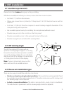
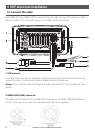
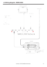
3 GPS Connector and cable
NMEA0183 OUT (+)
2 (Orange)
NMEA0183 IN (+)
5 (Yellow)
NMEA0183 IN (-)
4 (Green)
RS422 OUT (-)
3 (White)
RS232 OUT
7 (Blue)
RS422 OUT (+)
6 (Black)
RS232 IN
8 (Grey)
GROUND (Shield)
NMEA0183 OUT (-)
1 (Bare wire)
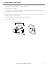
Line up the arrow on the GPS connector with the arrow on the GPS cable and plug together.
The pin details are shown for information.
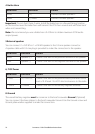
Pin /
Socket
Wire
color
GPS / MFD
(NMEA 0183)
AIS
(NMEA 0183 HS)
1 Shield
GROUND,
NMEA 0183 OUT (-)
4800bps RS232 OUT (-) 38.5 kbps
2 Orange NMEA 0183 OUT (+) 4800bps
3 White RS422 OUT (-) 38.5 kbps
4 Green NMEA 0183 IN (-) 4800bps
5 Yellow NMEA 0183 IN (+) 4800bps
6 Black RS422 OUT (+) 38.5 kbps
7 Blue RS232 OUT (+) 38.5 kbps
8 Grey RS232 IN Not used
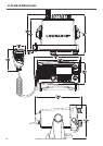
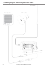
Note:The GPS connector on the radio is provided with a protective cover. If this connector
will not be used, please ensure the protective cover is fitted.
Lowrance - Link-8 Installation Instructions 13