


Feet, Fathoms,
Meters
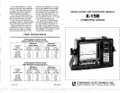
The
X-158 will
display
the
depth
in
feet,
fathoms,
or
meters. Al-
though
the unit will
revert back to
the feet mode
whenever
power
is
turned
off,
ills
simple
to
change
to
any
mode
you
wish
by pressing
the 2nd
key
and then 1
for
feet,
2nd
-
2
for
fathoms,
and
2nd
-
3 for meters.
When the unit is in
the Feet
mode, only
one
Il
will
be dis-
played.
In the
Fathom
mode,
two
12 L's
will be
displayed.
Three
Ii I! I.!
's will be
displayed
in the
meters mode.
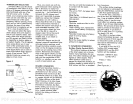
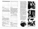
Example: Display
Fathoms
Press: 2nd
-
2
Result:
Figure
36
long pulses,
then the short
pulses
will be
cancelled
out,
and
only
the
desired information
(fish, bottom,
structure,
çtc.)
will be
displayed.
Of
course,
the transmitter's
pulse
length
would have to be increased
at the same
time so that the
re-
turn echoes would be
accepted by
the receiver.
This is
exactly
what
the Low-
rance
suppression
system
does.
The
transmitter's
pulse length
is
increased
by
the front
pane!
sup-
pression control,
and the receiver
"tracks" the
amount of increased
pulse length, cancelling
out
any
narrow noise
pulses,
and
display-
ing only
the return echoes from
fish or the
bottom,
etc.
(Notq:
Re-
ceiver
sensitivity
is not
diminished
at all
by
this
process.)
The
only
disadvantage
to
this
system
is
resolution,
or
the
ability
to
separate targets,
is
diminished
•when the
pulse length
is in-
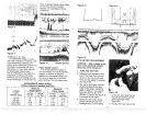
creased. A 200 is
(micro-second)
a transmitter
pulse
length
used on
the X-15B
when
power
is first
turned
on,
will
allow the unit to
display
two fish or
targets that
are
only
6
inches
apart.
In other
words,
if two fish that are 6
irches
apart
are
displayed
on
the
graph
paper, they
will show
up
as two
separate
arches when the
trans-
mitter is
operating
with a
200s
pulse length.
Now,
if we
increase
the transmitter's
pulse
length
to
400
is,
(by rotating
the
Suppres-
sor control
clockwise)
those
same
two fish arches
will blend
together
and show
up
as one fish or
pos-
sibly
even a "blob"
on the
paper.
With
a 400
p.s
transmit
pulse
width,
those same two fish will
have to be at least 12 inches
apart
before
they
will show
up
as
two
separate
arches on the
graph.
This is
why
it is
important
to leave
By looking
at the number
of
C's,
one can determine
the
depth
display
mode that
the unit is
in,
i.e., Feet-, Fathoms-,
Meters.
Transmit Pulse Width
The noise
suppression
system
in
the X-15B
is a
patented pulse
length
discrimination
suppression
circuit,
and is thGsaffle as the one
used
on
all the Lowrance's
varL
able
suppression
flashers
and
graphs. Basically,
it works on the
principle
that
most noise
pulses
are of
relatively
short duration, If
the receiver
circuit can be ad-
justed
so that it will
accept only
the
section
entitled 'Advanced
Op-
eration". This
chapter
will describe
several other
features
that will en-
able
the serious
operator
to
get
the
maximum benefit from
this
equipment.
We
urge
you
to read this
man-
ual
thoroughly
and
familiarize
yourself
with the controls. Al-
though
this is a
very
advanced
unit,
it is
easy
to
use,
thanks to
the
power
of the
micro-computer
and the
front
panel
controls.
Should
you require
extra
help,
or
just
have a
question,
please
call
our Customer
Service
Department
toll free
1-800-331-3889.
(Okla-
homa residents
call collect
-
1-918-437-6881.)
Or check the en-
closed lit for a
service center
in
your
area.
A
representative
will
be
happy
to
help you.
II
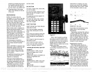
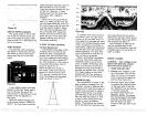
INSTALLATION
Mounting
—
The
depth
sounder
may
be in-
stalled in
any
convenient
area,
provided
the unit can be tilted
for
the best
viewing angle.
Hdles
in
the bracket
base allow wood
screw or bolt
mounting.
A wood
stiffener
may
be
required
on the
back of thin
fiberglass panels
to
support
the unit.
If
the desired location is closer
than 18"
to a
magnetic compass,
a trial
run should be made with
the unit
in
operation
to be sure
that the
compass readings
are
not
affected.
Power Connections
—
Twelve volt DC
power
for
the
depth
sounder
should be
supplied
by
the boat's 12 volt
electrical
sys-
tem. The
power
cable
may
be at-
tached to an
accessory
or
power
buss,
but if
you
have
problems
with electrical
interference,
the
cable should be attached
directly
to the
battery.
If a
longer
cable is
required,
use
ordinary
#18
lamp
cord
available
at
any
hardware or electrical
sup-
ply
store.
Splices
should be sol-
dered,
however,
if this isn't
done,
then use
crimp-type splices.
Tape
all
splices
with electrical
tape.
An
in-line fuse holder with
fuse
is
supplied
with the X-15B. Be cer-
tain to install
this as close to the
power
source
(such
as the boat
battery
or
power buss)
as
pos-
sible. This will
protect
both the
sonar unit
and
the
power
cable
in
the event
a short occurs.
Crimp
connectors are
supplied
to
attach
the fuse holder to the
power
cable. The red
wire in the
power
cable is the
positive
conductor.
The black wire
is the
ground
or
negative
conductor.
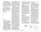
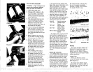
The
graph
is
protected
from ac-
cidental
polarity
reversals and no
damage
will
occur if the wires are
reversed.
The unit will not
operate
until the
proper polarity
is
applied.
ii—
I
-
'—'U
18
Figure
2
Ground
Negative)
3
PDF compression, OCR, web-optimization with CVISION's PdfCompressor