


© MEDC 2001 06/01
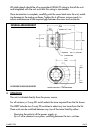
GENERAL ARRANGEMENT
All cable glands should be of an equivalent NEMA/IP rating to that of the unit
and integrated with the unit such that this rating is maintained.
Once termination is complete, carefully push the cover back onto the unit, avoid-
ing damage to the mating surfaces. Tighten the 6 off cover screws evenly, to
ensure maintenance of the required gap between the cover and enclosure.
3. OPERATION
The unit is initiated directly from the power source.
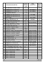
For all versions, a 5-way DIL switch selects the tone required from the list shown.
The DB3P includes two 5-way DIL switches to select any two tones from the list.
These units can be switched between any two of the tones listed by either:-
· Reversing the polarity of the power supply, or
· By a 3 wire common +ve system, switching between the two –ve lines.
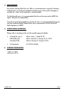
10
11
/16"
271mm
Ø 4
5
/8" / 117mm
Ø 6
11
/16" / 170mm
FIXING HOLE Ø
1
/2" / 13mm
FIXING HOLES Ø ALL
11
/32" / 9mm (2 POS.)
2 x
1
/2" NPT ENTRIES MAX
7
19
/32"
193mm
1
3
/16"
30mm
1
3
/16"
30mm
POSITION 2 IS USED IF ONLY 1 x
1
/2" NPT ENTRY REQUIRED
2
3
/32"
53mm
ALL DIMENSIONS IN INCHES AND MILLIMETERS