


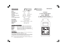
OPERATION:
• Connect the supplied 12 VDC power
adapter to the meter and to the mains.
• Connect the pH and ORP electrode
to the BNC socket of the meter.
• Always remove the electrode protec-
tive caps before taking any
measurement. If the electrodes have
been left dry, soak the tip (bottom 2.5
cm) in rinse solution (M10000B) for a
few minutes to reactivate them.
• Make sure that the meter has been
calibrated before taking any measure-
ments (see Calibration Procedure).
• Immerse the tip (2.5 cm) of the electrodes into the samples.
• Turn the instrument on by pressing the ON/OFF key.
• Allow the reading to stabilize and the meter will start con-
tinuous monitoring.
• A blinking alarm LED will indicate when the measured pH
value is higher than the setpoint and ORP value is lower
than setpoint.
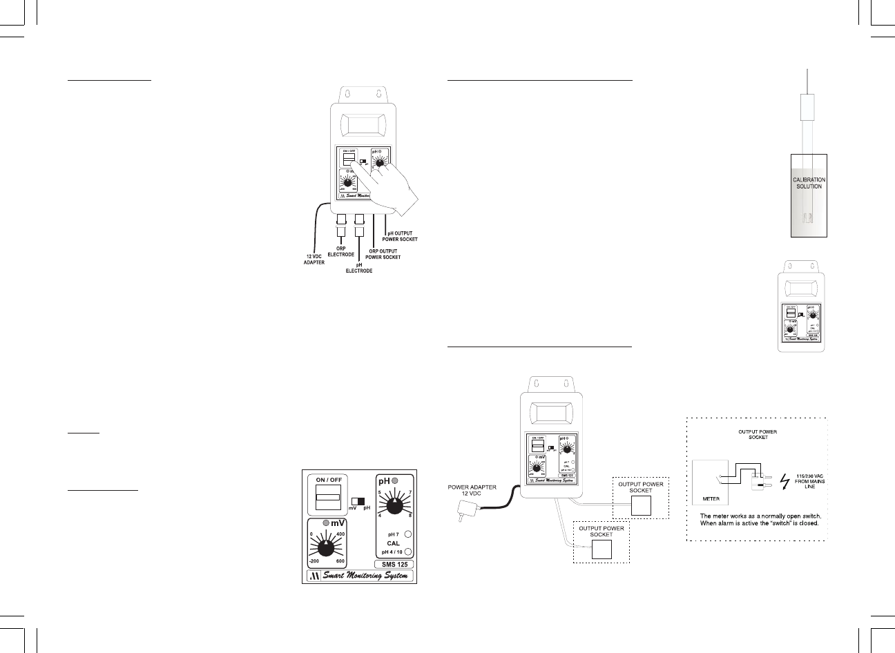
• When the alarm LED is blinking, there is power in the
output power socket.
NOTE
: The output power contact has no protection fuse inside the
meter. It is recommended to protected it outside, against
failure.
SETPOINT:
• The setpoint can be selected by ad-
justing the knob to the desired value.
• The selectable range for SMS125 is from
4 to 8 for pH and from -200 to 600 mV
for ORP.
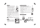
CALIBRATION PROCEDURE:
• Remove the protective cap from the pH electrode.
• Immerse the electrode tip into a new sachet of pH 7 calibra-
tion solution and allow the reading to stabilize.
• Adjust the OFFSET calibration trimmer (on the front) to
display "7.00 pH".
• Open a new sachet of pH 4 calibration solution and use a
small quantity to rinse the electrode.
• Immerse the electrode tip inside the pH 4 sachet and allow
the reading to stabilize.
• Adjust the SLOPE calibration trimmer (on the front) to dis-
play "4.00 pH".
• The calibration is now complete and the meter is ready to
take measurements.
• It is suggested to recalibrate the meter at least once a
month, after prolonged warehousing time and after pH elec-
trode replacement.
INSTALATION PROCEDURE: