


46
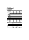
Standard Specifications
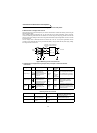
Note: 1. The applicable inverter capacity is the sum total of the inverter capacities (up to six inverters). For the
FR-V500 series inverter, the capacity of the main circuit smoothing capacitor is larger than that of other
types of transistorized inverter with same capacity. Therefore, use the substituted inverter capacity in the
table below for selection.
Example: Applicable inverter capacity for the FR-CV-15K
→ •FR-A700 series
1) FR-A720-15K
2) FR-A720-11K + FR-A720-3.7K
•FR-V500 series
1) FR-V520-11K
2) FR-V520-7.5K + FR-V520-2.2K
Make selection so that the sum of the rated currents of the used motors does not exceed the applicable
current.
2. The power supply capacity changes with the values of the power supply side inverter impedances
(including those of the input reactor and cables).
3. Since the dedicated stand-alone reactor is connected, a voltage may drop to cause motor torque
shortage or a current may increase to overheat the motor.
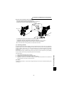
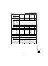
4. The FR-CV-37K, 55K and FR-CV-H37K, H55K can be used as either a heat sink outside mounting
structure model or an enclosure inside installation structure model by changing its mounting foot
position. The mounting foot is factory-set in the heat sink outside mounting position.
(Refer to page 8 for changing the mounting foot position.)
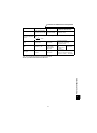
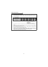
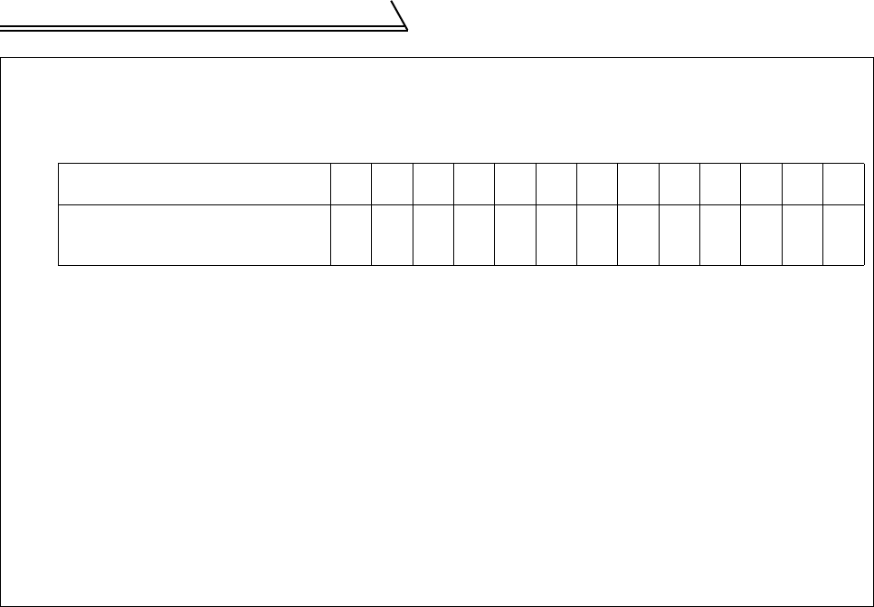
Actual capacity [K]
of the FR-V500
1.5 2.2 3.7 5.5 7.5 11 15 18.5 22 30 37 45 55
Substituted capacity [K]
of the FR-V500 for use in combination
with the FR-CV.
2.2 3.7 5.5 7.5 11 15 18.5 22 30 37 45 55 55