


22
Wiring
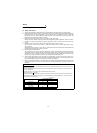
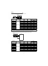
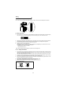
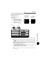
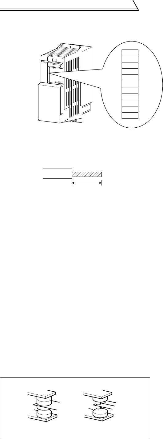
(2) Terminal block layout
In the control circuit of the power regeneration common converter, the terminals are arranged as shown below:
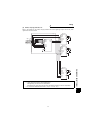
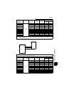
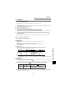
(3) Wiring procedure
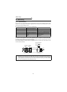
1) For the wiring of the control circuit, strip the sheaths of the cables and use them as they are. Over-stripping
may cause a short circuit with the neighboring cable.Under-stripping may cause cable disconnection.
2) When using bar terminals or solid cables for wiring, use those of not more than 0.9mm (0.04inch) in diameter.
If the diameter is greater than 0.9mm (0.04inch), the screw threads may be damaged when tightened.
3) Loosen the terminal screw and insert the cable into the terminal.
4) Tighten the screw to the specified torque.
Undertightening can cause cable disconnection or malfunction.Overtightening can cause the screw or unit to
be damaged, resulting in a short circuit or malfunction.
Tightening torque: 0.25N•m to 0.49N•m
*Use a screwdriver of No. 0.
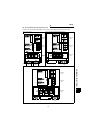
2.2.4 Design information
1) If the machine must be prevented from restarting at recovery of power after a power failure, provide a magnetic
contactor in the primary side of the power regeneration common converter and also make up a sequence that
will not turn on the start signal of the inverter.
If the start signal (start switch) of the inverter is held, the inverter will automatically restart at recovery of power.
2) Configure up a circuit that will always turn off the main circuit power supply terminals R2/L1, S2/L2, T2/L3 as
soon as the power supply phase detection terminals R/L11, S/L21, T/MC1 turn off.
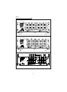
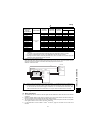
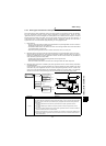
3) Since the input signals to the control circuit are on a low level, use two parallel micro signal contacts or a twin
contact for contact inputs to prevent a contact fault.
4) Do not apply a voltage directly to the alarm output signal terminals (A, B, C).
Always apply a voltage to these terminals via a relay coil, lamp, etc.
5) Make sure that the specifications and rating match the system requirements.
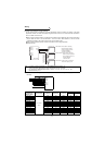
Note: Wire the stripped cable after twisting it to prevent it from becoming loose.
3) Low-level signal contacts
A
B
C
P24
RES
SD
SD
RDYB
RSO
SE
RDYA
7mm (0.28inch) 1mm (0.04inch)
+
_
Twin contact
Low-level signal contacts