


15
Wiring
INSTALLATION AND WIRING
2
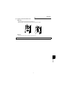
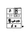
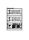
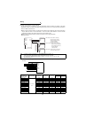
(2) Terminal block layout of the power circuit
In the main circuit of the power regeneration common converter, the terminals are arranged as shown below:
FR-CV-7.5K/11K(-AT) FR-CV-15K(-AT), FR-CV-H7.5K/H11K/H15K(-AT)
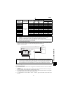
FR-CV-22K/30K(-AT), FR-CV-H22K/H30K(-AT)
P
N
S
R
T
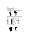
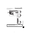
<DC power output
terminals>
Connect to inverter
P and N terminals.
<Supply phase detection
terminals>
Connect to FR-CVL R,S and
T terminals (main supply).
<AC power supply input terminals>
Connect to FR-CVL R2, S2 and T2
terminals (secondary side).
Screw size
(M6)
L+
L-
L11
L21
MC1
L1 L2 L3
R2 S2 T2
Screw size
(M4)
Screw size
(M5)
Screw size
(M5)
Screw size
(M4)
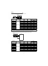
L+
L-
L11
L21
MC1
L1 L2 L3
R2 S2 T2
P
N
S
R
T
<DC power output
terminals>
Connect to inverter
P and N terminals.
<Supply phase detection
terminals>
Connect to FR-CVL R, S and
T terminals (main supply).
<AC power supply input terminals>
Connect to FR-CVL R2, S2 and T2
terminals (secondary side).
Screw size
(M6)
Screw size
(M4)
Screw size
(M5)
Screw size
(M5)
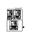
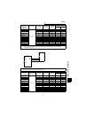
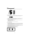
L+
L-
P
N
S
R
T
L11
L21
MC1
L1 L2 L3
R2 S2 T2
<DC power output terminals>
Connect to inverter P and N
terminals.
<Supply phase detection terminals>
Connect to FR-CVL R, S and T
terminals (main supply).
<AC power supply input terminals>
Connect to FR-CVL R2, S2 and T2
terminals (secondary side).
Screw size
(M6)
Screw size
(M4)
Screw size
(M8)
Screw size
(M8)