


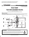
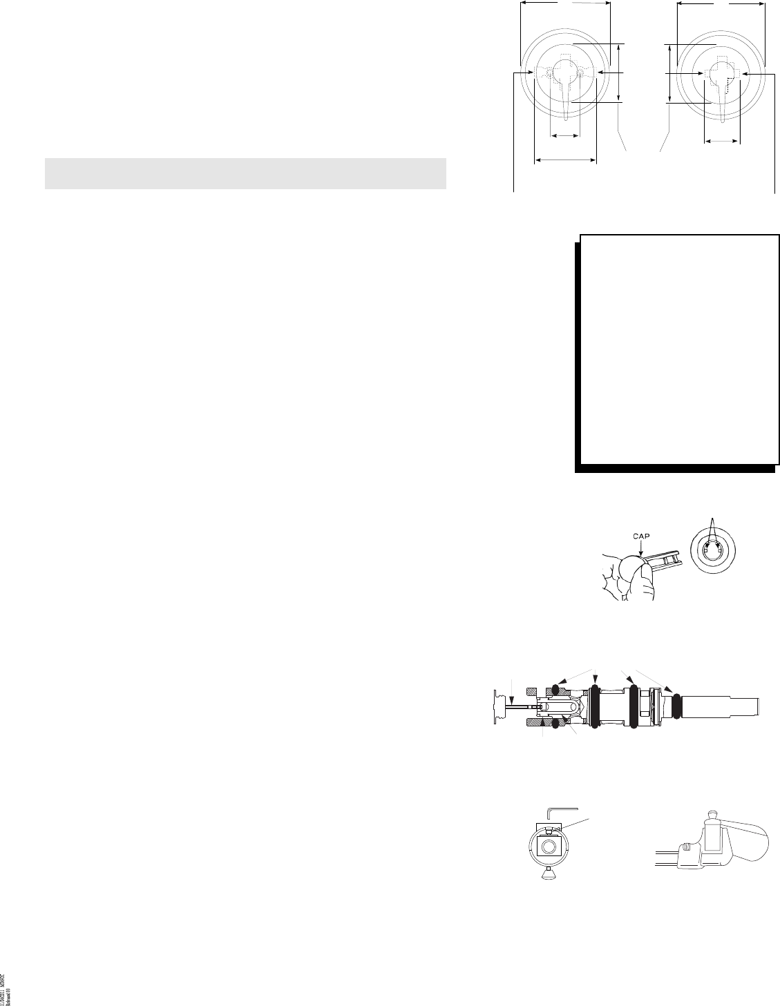
MT692C
WITHOUT STOPS
WITH STOPS
7"
7"
SHOWER
SHOWER
SUPPLY
TUB
TUB
SUPPLY
SUPPLY
2-3/4" C.C.
& I.P.S.
2-5/16" C.C.
& I.P.S.
4-13/16" C.C.
4-5/16"
NOMINAL
4-1/2"
PLASTER
GROUND
SIZE AND
WALL
OPENING
C.C. I.P.S.
CLAMP
SCREW
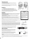
CAUTION
This valve is equipped with the Moen
long-life POSI-TEMP cartridge,
designed for smooth, trouble-free
operation. When soldering do not heat
valve any higher than necessary to flow
the solder. Overheating may damage
the cartridge or rubber stop valves.
Following this direction will allow you
to solder without removing the car-
tridge or rubber stop valves.
WARNING: The cartridge and rubber
stop valves MUST be removed before
either brazing or resistance (electric)
soldering.
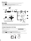
CLIP/BARS
ORIENT THE CLIP IN THE SPOOL AND THE
CAP FINGERS AS SHOWN ABOVE.
CAP
O-RINGS
CLIP/BARS
STEM ASSEMBLY
BALANCE
SPOOL
Stop Operation
CC - This type is integral with casting, actuated by screwdriver, and require a 90° turn to
open or close. When the screwdriver slot is vertical, the rubber stop is closed, and when
the slot is horizontal, the rubber stop is open.
IPS - This type has been added to the basic shower casting and is actuated by a screwdriv-
er. The stop is opened by rotating in a counterclockwise direction until it stops and closed
by rotating in a clockwise direction until it bottoms.
MAKE SURE ALL WATER SUPPLIES ARE OFF.
Note the word "TOP" on the casting. Install casting with the TOP facing UP. If the valve is to be
used for a shower only, plug the bottom outlet. If the valve is to be used for both a shower and
a tub, connect the top outlet to the shower and the bottom outlet to the tub. Secure all pipes
and the shower and tub drop ells. Use thread seal tape on all threads.
Rough-In
Flushing
IMPORTANT: Before closing all wall openings, pressure test valve and complete sys-
tem using flushing instructions
Pipe chips, sand and other solids found in new and renovated plumbing can damage the sealing surfaces
of the cartridge causing a leak or cause the spool to become blocked. To avoid damage, DO NOT
TURN ON SUPPLY VALVES until instructed below.
Make sure both hot and cold supplies are off. Rotate the cartridge stem until the notched flat points up to
relieve pressure and insure complete shut-off. Remove the cartridge assembly (see "Disassembly").
Slowly turn on both hot and cold supplies and thoroughly flush out the body and lines. Close the hot and
cold supplies and replace the cartridge assembly (see "Reassembly"), turn on both supplies and check the system
for leaks.
If the balancing spool becomes stuck, it will be apparent at the trim-out test in that the valve will deliver only a
small trickle of water, or it will deliver only hot or cold water. If this occurs, proceed as follows:
Make sure that both the hot and cold water service lines are "ON". Also make sure that both rubber stop valves
are open (stop models). The valve WILL NOT OPERATE unless both supplies are "ON".
If the valve still does not function properly, turn off BOTH the hot and cold supplies and remove the cartridge
assembly. A cartridge twisting tool is required for this. The inner spool in the cartridge assembly should shake
back and forth freely. If this does not happen, remove the stem assembly from the cartridge sleeve, remove the
cap from the stem assembly and remove the balance spool. Sometimes the stem assembly may have to be jarred
to free the spool. Carefully clean any foreign material from the balance spool and stem assembly and reassemble
(see illustration). CAUTION: DO NOT DAMAGE O-RINGS. The spool should move back and forth after the stem
assembly is cleaned. If spool still does not free up, replace the entire cartridge assembly.
Make sure O-rings are free of foreign material and are lubricated. Re-assemble stem
assembly into cartridge sleeve. Re-assemble cartridge into valve. (See "Reassembly").
Turn both water supplies on. The valve should function properly.
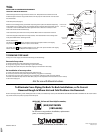
Slip-Fit spouts
C.C. SPOUT: The Moen Slip Fit spout is designed with an O-ring seal. It is specifically
designed for installation with copper water tube. Lookout must be free from burrs
inside and out. The edge must not be rolled inward from a dull tubing cutter. The
outside surface must be free from nicks and scratches.
Press and twist the spout onto the lookout upside down. Tighten the clamp screw
with a 5/32" hex wrench until it just starts to bind. Turn spout upright into position
against the wall and finish tightening the clamp screw by hand. The use of pliers or
another wrench on the hex wrench is not necessary. Do not overtighten.
IPS SPOUT:
CAUTION: This spout is A.B.S. plastic and will crack when in contact with some pipe thread compounds.
Please read the pipe compound label to be certain. We recommend using thread seal tape thread sealant.
Screw tub spout onto pipe and tighten by hand. If final turn by wrench is needed, use small wrench with smooth jaws;otherwise, pad wrench teeth with rag.
Pull outward on spout while tightening to avoid scratching wall. DO NOT INSERT TOOL INTO SPOUT END TO TURN SPOUT.