


HPLA/HPHA-SERIES 36" WALK-BEHIND TROWEL — OPERATION AND PARTS MANUAL — REV. #3 (07/06/10) — PAGE 35
HPLA/HPHA-SERIES 36" TROWEL — MAINTENANCE
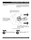
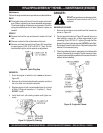
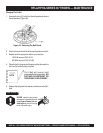
2. Trowels manufactured prior to June of 1982 require that the
distance from the end of the adjusting bolt and the fixture arm
must be 7/8" (Figure 45). Conversely, trowels manufactured
after June of 1982 require that the distance from the end of
the adjusting bolt and the fixture arm must be 1/2".
10. Reinstall lower wear plate,
thrust collar
and
upper wear
ring
in the
reverse order
that they were dis-assembled onto
the spider shaft. Make sure that there is little or no lateral
movement between the thrust collar and the spider shaft.
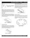
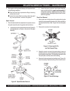
3. Un-screw the locking bolts on the adjustment tool, and place
the trowel arm into the adjustment fixture channel as shown
in (Figure 48). A
thin shim
may be required to cover the
blade holes on the trowel arm. Make sure to align the trowel
adjustment bolt with the fixture adjustment bolt.
4. Using an allen wrench, tighten the locking bolts on the
adjustment tool and securely lock the trowel arm in place.
5. Loosen the locking nut on the trowel arm lever, then turn the
trowel arm adjusting bolt until it barely touches (.010") the
adjusting bolt on the fixture.
6. After the correct adjustment has been made, tighten lock nut
on trowel arm lever to lock in place.
7. Loosen locking bolts on adjustment fixture, and remove
trowel arm from fixture.
8. Repeat steps 2-7 for the remaining trowel arms.
Re-Assembly
1. Clean and examine the upper/lower wear plates and thrust
collar. Examine the entire spider assembly. Wire brush any
concrete or rust build-up. If any of the spider components are
found to be damaged or out of round, replace them.
2. Make sure that the bronze trowel arm bushing is not damage
or out of round. Clean the bushing if necessary. If the bronze
bushing is damage or worn, replace it.
3. Reinstall bronze bushing onto trowel arm.
4. Repeat steps 2 -3 for each trowel arm.
5. Make sure that the spring tensioner is in the correct position
to exert tension on the trowel arm.
6. Insert all trowel arms with levers into spider plate (with bronze
bushing already installed) using care to align grease hole on
bronze bushing with grease hole fitting on spider plate.
7. Lock trowel arms in place by tightening the hex head zerk
grease fitting and jam nut.
8. Re-install the blades back onto the trowel arms.
9. Install stabilizer ring onto spider assembly.
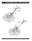
11. Carefully lift
the upper trowel assembly
, line up the key-
way on gear box main shaft and insert into spider assembly.
12. Reinstall square head cone point into spider plate and
tighten in place. Tighten jam nut. Use care in making sure
point of set screw engages groove in gear box main shaft.
13. Lubricate all grease points (zerk fittings) with premium
"
Lithum 12"
based grease, conforming to NLG1 Grade #2
consistency.
Testing
1. Place trowel in test area, start engine and test trowel for
smoothness.
2. If trowel bounces has excessive vibration or does not run
smoothly repeat alignment procedure.
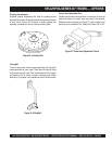
NOTE
Before removing the blades,
please note the orientation of the
blade on the trowel arm.
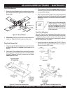
2. Remove the three bolts and lock washers that secure the
blade to the trowel arm. Remove the blade.
3. Using a wire brush, scrape all concrete particles and foreign
debris from the trowel arm.
4. Install the new trowel blade onto the trowel arm. Make sure
blade is installed correctly, maintaining the proper orienta-
tion for direction of rotation
.
5. Reinstall
the three bolts and lock washers that secure the
blade to the trowel arm. Tighten all three bolts securely.
6. Repeat steps 2-5 for all remaining blades.
Changing a Blade
Whiteman recommends that
all the blades be changed at the
same time
. The machine may wobble or bounce if only some of
the blades are changed at one time.
1. Place the machine on a flat, level surface. Adjust the blade
pitch control to make the blades as flat as possible. Note the
blade orientation on the trowel arm.