


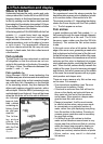

Correct installation is critical to the performance
of the FISH 4500/4600. There are two compo-
nents to install, the display unit and the trans-
6 Installation and Maintenance
ducer. It is vital to read the entire installation
section of this manual before attempting to
install the components.
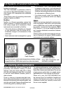
6-1 What comes with this product?
Standard configuration:
• FISH 4500/4600 display unit
• Power cable
• Mounting bracket (screws included)
• Warranty registration card
• This manual
• Sun cover for display unit
• Flush mounting kit
• Dual frequency transom transducer (includes
cable kit and screws)
• Transom Mount Transducer Installation Manual.
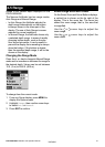
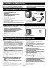
6-3 Mounting and removing the display unit
• TRACKER series of chartplotters
• Through hull dual frequency transducer
• Through hull speed/temperature transducer
• Fuel flow kit (single or twin engine)
• Replacement paddle wheel
• SmartCraft Gateway
• REPEAT 3100 (see section 6-6 Systems of
several instruments).
• Diesel 3200 for fuel flow on diesel engines
There are two mounting arrangements:
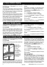
• Flush mounting requires a solid panel with
access behind for wiring and mounting screws.
After flush mounting, the FISH 4500/4600
cannot be tilted or moved after installation
to reduce any unwanted glare or reflections.
Carefully select the best viewing position before
installation. This would generally be in a shaded
area.
• Bracket mounting requires a panel for mount-
ing the bracket. Ensure that the panel is not
likely to deform and is not subject to excessive
vibration. The bracket can be tilted and rotated
so the FISH 4500/4600 can be removed after
each use.
Select a position where the display unit will be:
• At least 4” (100 mm) away from the com-
pass.
• At least 12” (300 mm) away from any radio
transmitter.
• At least 4 ft. (1.2 m) away from any antenna.
• Easy to read by the helmsman and crew
TRACKER
5500/5600 chartplotter
Fuel flow kit
6-2 Options and Accessories
while underway.
• Protected from physical damage during
rough sea passages.
• Easy to access the 12 / 24 V DC power source.
• Convenient to route the transducer cables.
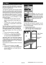
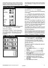
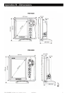
Flush Mounting
1. Cut a hole in the bulkhead for the display unit
using the flush mount template.
2. Drill four holes for the mounting studs using
the flush mount template.
3. Screw the four studs into the brass inserts in
the back of the display unit.
4. Sit the display unit in place and fit the
washers and nuts to the studs.
Bracket Mounting
1. Fix the mounting bracket onto the boat using the
three stainless steel screws. Do not overtighten the
screws, as the bracket may not rotate.
2. Push the display unit onto the mounting
bracket and tighten it firmly using the knob on
the mounting bracket.
3. Attach the cables.
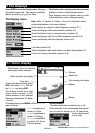
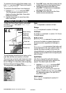
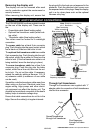
Display unit
Screws
Power cable
Mounting bracket
Dual frequency
transom transducer
Please consult your Navman dealer for more
information.
FISH 4500/4600 Installation and Operation Manual 27
NAVMAN