


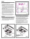
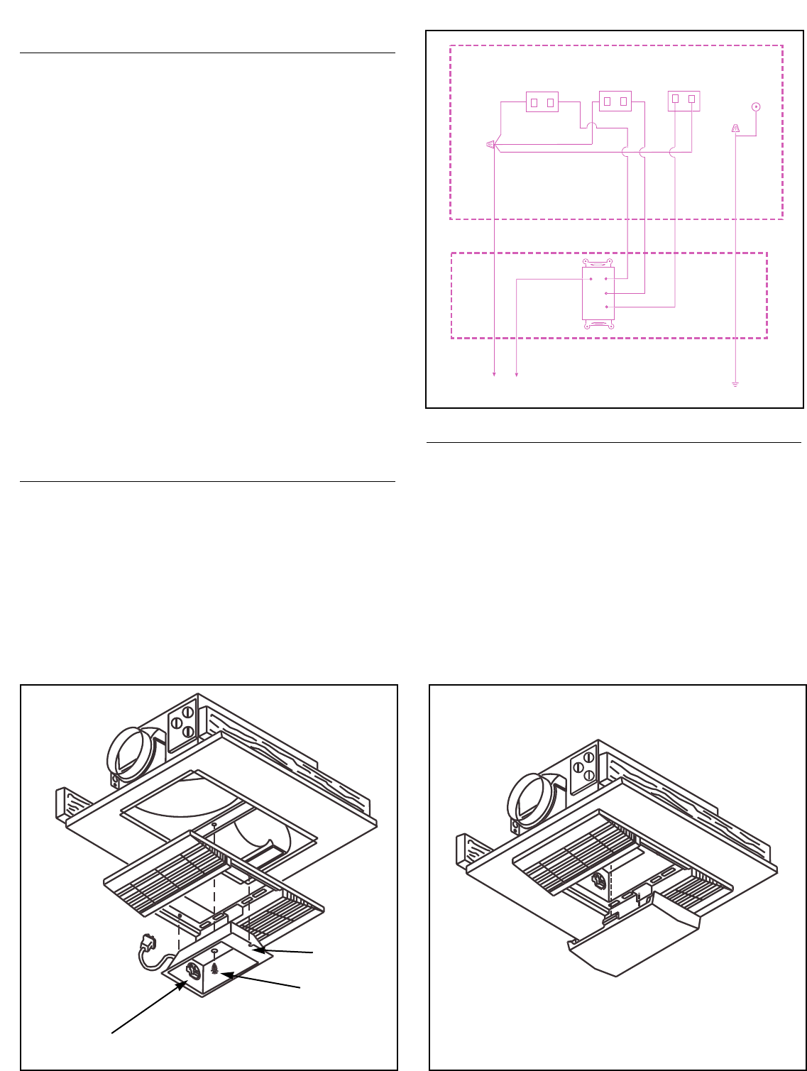
HEATER JUNCTION BOX
LIGHT
RECEPTACLE
WHITE
WHITE
RED
GREEN
WALL SWITCH BOX
WHITE
BLACK
120VAC LINE
SUPPLY
GROUND
LIGHT
HEAT
VENT
WHITE
BLACK
BLUE
VENT
RECEPTACLE
HEAT
RECEPTACLE
(WHITE)
FIGURE 2
WIRING
All wiring must comply with local and national codes
and unit must be properly grounded.
1. Run 120VAC, 60Hz supply wiring to the wall switch (not
provided). The unit must be wired on a separate 20
Amp circuit.
2. Run wiring from the switch to the housing junction box.
Loosen screw holding exterior wiring compartment cover
and remove cover. Interior wiring compartment may be
removed if necessary by loosening screw in keyhole slot in
cover. Remove knockout(s) as required and install
approved box connector.
3. Refer to fig. 2. Connect white wires in junction box to
white (neutral) supply wire. Connect the blue wire in the
junction box to the supply wire from the vent switch.
Connect the black wire to the supply wire from the light
switch. Connect the red wire in the junction box to the
supply wire from the heat switch. Connect green ground
lead in the junction box to the supply ground.
4. Replace wiring compartment cover and tighten screw to
secure.
5. Insert vent motor plug in vent receptacle on wiring
compartment cover. Insert plug from heater assembly into
the white socket of the wiring compartment cover.
DUCTING
1. Snap plastic duct adapter and damper assembly over
flanged opening on housing. Connect 4" round duct to the
duct adapter and secure with duct tape. The duct should
be run to the outside of the structure through the roof or
wall cap. For maximum performance keep duct runs as
short and as straight as possible.
FIGURE 3
FIGURE 4
LIGHT SOCKET
REFLECTOR
LENS
REFLECTOR
MOUNTING
SCREW
USE COMPACT FLUORESCENT
LAMP, NEMA TYPE
CFQ13W/GX23/827 (PURCHASE
LOCALLY)
MOUNTING REFLECTOR AND GRILLE
1. Place reflector in the opening in the center of the grille.
The notches in the reflector should fit over the pegs on
either side of the opening. Insert plug from lamp ballast
into lamp receptacle on wiring compartment.
2. Place 1" screw, provided, through the center hole in the
reflector and thread it into the hole in the mounting bracket
running across the housing. Tighten the screw just
enough to hold the grille firmly against the ceiling.
3. Install a 13 watt Compact Fluorescent lamp, NEMA type
CFQ13W/GX23/827. (Not provided)
4. Snap lens into position in center of grille. To remove the
lens for relamping, gently pry along the side of the lens
with a screwdriver to disengage the snap in tabs while
pulling down on the lens.