


6 C528M-E (4/03)
2. Electrical Connections - Follow the correct instructions for your control model.
Cable Distances:
Pan/Tilt
or Scanner Refer to the installation manual for the specific scanner or pan/tilt to be used with the control.
Lens The following lens distances are the approximate maximum recommended under the following conditions:
• Based on a 35 mA load @ 12 VDC
• Single lens function activation
• 10% line loss in voltage at the lens motor
22 AWG (0.3 mm
2
) 1,062 ft (323 m)
20 AWG (0.5 mm
2
) 1,688 ft (514 m)
18 AWG (1.0 mm
2
) 2,686 ft (818 m)
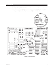
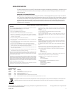
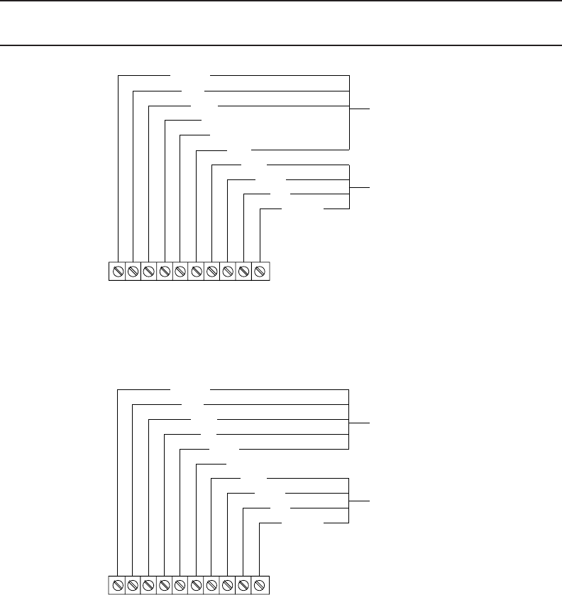
MPTAZ24DT and MPTAZ24DT/220 - Wire the connecting cable from the pan/tilt or scanner to the control. Refer to one
of the following wiring diagrams: Figure 2 (scanners) or Figure 3 (pan/tilts). Proceed to step 3.
NOTE: When a relay box (RB24/RB115) is used with a scanner, the AUTO SCAN mode requires special connections;
consult factory for details.
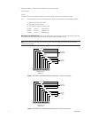
Figure 2. MPTAZ24DT, MPTAZ24DT/220 Wiring Diagram for Scanners and Lenses
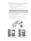
Figure 3. MPTAZ24DT, MPTAZ24DT/220 Wiring Diagram for Pan/Tilts and Lenses
PT COMM
LEFT
RIGHT
UP
DOWN
AUTO
ZOOM
FOCUS
IRIS
LENS COM
TO SCANNER
CONNECTOR
TO LENS
CONNECTOR
1 2 3 4 5 6 7 8 9 10
CONTROLLER OUTPUT
TERMINAL STRIP
PT COMM
LEFT
RIGHT
UP
DOWN
AUTO
ZOOM
FOCUS
IRIS
LENS COM
TO PAN/TILT
CONNECTOR
TO LENS
CONNECTOR
1 2 3 4 5 6 7 8 9 10
CONTROLLER OUTPUT
TERMINAL STRIP