Pelco Manual C554M-A (5/98) 3
REVISION HISTORY
Manual # Date Comments
C554M 4/95 Original version.
8/96 Changed fusing values for fuse #F1, Figure 1.
8/97 Changed fusing values for fuse #F2, Figure 1 per ECO#
93-362.
C554M-A 5/98 Rev A. Changed manual to new format and manual
pagination. Included the CE version metal box receiver/
drivers.
LIST OF ILLUSTRATIONS
Figure Page
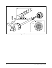
1 Connector Assembly .........................................................................12
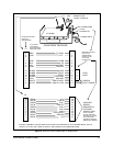
2 Receiver Control Output/Input Pin Assignments............................... 13
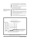
3 Wiring Diagram for Pre-position Alarm Outputs ................................14
4 Jumper Settings on the Receiver/Driver PC Board ...........................18
5 Auxiliary Functions Wiring Diagram ..................................................19
6 External Device Wiring Diagram .......................................................19
7 AC Input and Fuse Values ................................................................21
8 CX9000 Series Dimension Drawing (Fiberglass Box) ......................25
9 CX9000 Series Dimension Drawing (Painted Metal Box–CE Version) ..26
10 CX9000 Series Dimension Drawing (Alodine Metal Box) .................26
LIST OF TABLES
Table Page
A Video Coaxial Cable Wiring Distances .............................................10
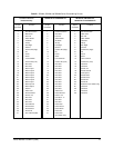
B SB1900, SS2000 and SB2600 Series Preset Wiring Pinouts ...........15
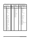
C PT280, PT520, PT550, PT570, PT680, PT1250, PT1280 and
SB2800 Series Preset Wiring Pinouts ..............................................16
D Lens Preset Wiring Pinouts ...............................................................17
E 24 VAC Wiring Distances ..................................................................20


