


Connecting the power cord (2)
IMPROPER CONNECTION MAY RESULT IN SERIOUS DAMAGE
OR INJURY INCLUDING ELECTRICAL SHOCK, AND
INTERFERENCE WITH THE OPERATION OF THE VEHICLE´S
ANTILOCK BRAKING SYSTEM, AUTOMATIC GEARBOX AND
SPEEDOMETER INDICATION.
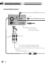
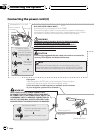
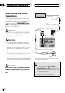
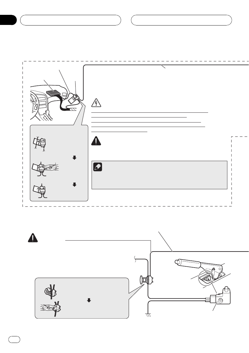
Pink (CAR SPEED SIGNAL INPUT)
This connection is unnecessary for AVIC-F700BT.
The mobile navigation system is connected here to detect the distance the
vehicle travels. Always connect the vehicle´s speed detection circuit. Failure
to make this connection will increase errors in the location display.
LIGHT GREEN LEAD AT POWER CONNECTOR IS
DESIGNED TO DETECT PARKED STATUS AND MUST
BE CONNECTED TO THE POWER SUPPLY SIDE OF THE
HANDBRAKE SWITCH. IMPROPER CONNECTION OR
USE OF THIS LEAD MAY VIOLATE APPLICABLE LAW
AND MAY RESULT IN SERIOUS INJURY OR DAMAGE.
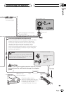
Light green
Used to detect the ON/OFF status of the handbrake. This lead must be
connected to the power supply side of the handbrake switch.
If this connection is made incorrectly or omitted, certain functions
of your navigation system will be unusable.
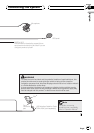
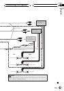
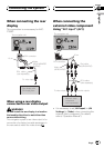
The position of the speed detection circuit and the position of the
parking brake switch vary depending on the vehicle model. For details,
consult your authorised Pioneer dealer or an installation professional.
Speed detection circuit lead
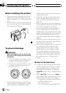
Connection method
Power supply side
Earth side
Handbrake switch
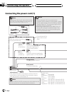
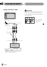
3 m
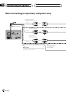
Pass the extension
cord and the lead for
the speed detection
circuit through this
hole.
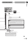
Clamp firmly
with needle-
nosed pliers.
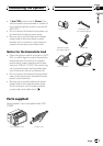
Connection method
Clamp the parking brake switch
power supply side lead.
Clamp firmly with needle-nosed
pliers.
Close the cover.
Vehicle injection
computer
Connector
WARNING
CAUTION
Note
WARNING
It is strongly suggested that the speed pulse wire be connected for
accuracy of navigation and better performance.
Connecting the System
Engb
12
Section
03