


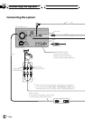
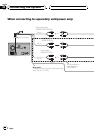
Connecting the power cord (1)
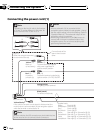
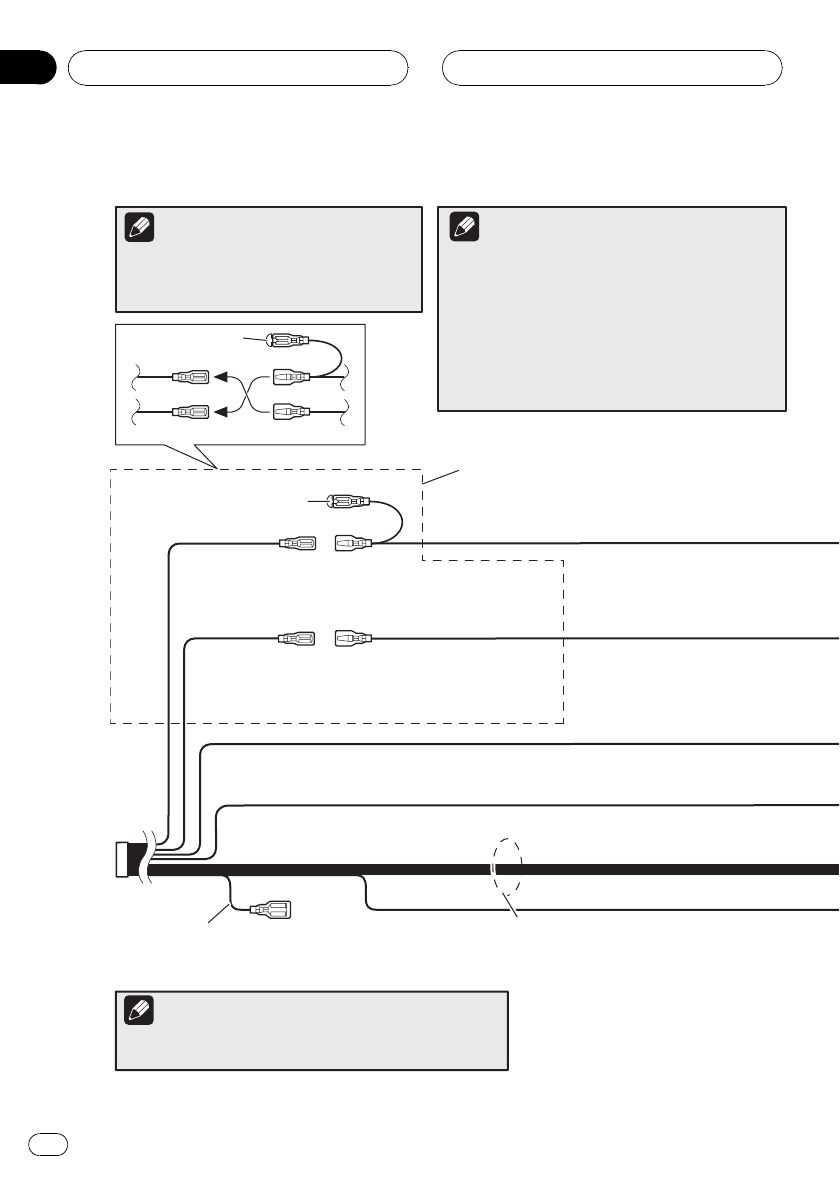
ISO connector
*1
*2
*4
*3
*5
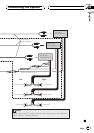
Speaker leads
White: Front left
White/black: Front left
Grey: Front right
Grey/black: Front right
Green: Rearleft or Subwoofer (*9)
Green/black: Rear left or Subwoofer (*9)
Violet: Rear right or Subwoofer (*9)
Violet/black: Rear right or Subwoofer (*9)
Depending on the kind of vehicle, the function
of *3 and *5 may be different. In this case, be
sure to connect *2 to *5 and *4 to *3.
Connect leads of the
same colour to each
other.
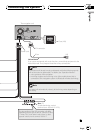
Cap (*1)
When not using this terminal,
do not remove the cap.
Yellow (*3)
Back-up
(or accessory)
Red (*5)
Accessory
(or back-up)
Yellow (*2)
To terminal always supplied
with power regardless of
ignition switch position.
Red (*4)
To electric terminal controlled by
ignition switch (12 V DC) ON/OFF.
Orange/white
To lighting switch terminal.
Black (earth)
To vehicle (metal) body.
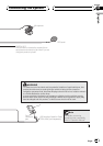
In some vehicles, the ISO connector may be divided into two.
In this case, be sure to connect to both connectors.
Yellow/black
If the vehicle can send a mute signal to this terminal, the
mute function can be activated on this navigation system
when the terminal is connected to *8.
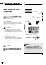
Note
Note
Notes
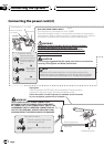
· When a subwoofer (*9) is connected to this
navigation system instead of a rear speaker, change
the rear output setting in the Initial Setting. (Refer to
“Operation Manual”.) The subwoofer output of this
navigation system is monaural.
· When using a subwoofer of 70 W (2Ω), be sure to
connect with violet and violet/black leads of this
navigation system. Do not connect anything with
green and green/black leads.
Connecting the System
Engb
10
Section
03