


Part 11
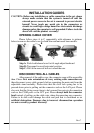
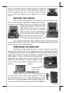
guide to mount the interface bracket and fix it to the rear
connect area of the system as in the right picture. Route the
VGA through the cable exit of the base stand to the main
unit. Connect the attached power adaptor for its power
source.
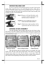
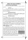
ROUTING THE CABLES
Place all the cables required for connections to the main unit except
those for the integrated attachment through the front part
inside the stand assembly. Be sure not to damage any cable
during this operation. The joint of the
DB9 RS232 cable of the external
devices and the RS232 conversion
cable if used is most recommended to
be kept inside the base stand assembly.
Now, turn the adjustable stand assembly back to normal orientation
and arrange all cables to come out of the area for mounting main unit from the
bottom edge for ease of later operation.
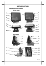
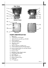
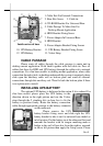
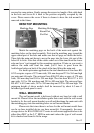
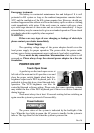
PREPARING THE MAIN UNIT
On the back of the main unit, there is a service window among the 4
matching pegs. Remove the service window lock screw to find several jumpers.
The jumpers in this window are designated for VGA port and COM port power
supply function. Please consult your dealer for technical support on setup of
these jumpers. Please note that only those qualified
technicians may adjust in the service window with
information from Posiflex and the contents in the
service window may change without notice as time
develops.
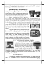
SIDE MOUNT UPGRADE KIT
Remove the 2 circled screws in last picture above
to remove the cover for side mount upgrade kit. Take out
the cable inside this cover as circled in right picture and
remove the 2 shorting jumpers inside and then connect it to
connector inside the side mount upgrade kit like SD400 as
Route Cables through Front Part
Connect this End to Main Unit
Service Window
Lock Screw
Jumpers