


III. I n s t a l l a t i o n
A. Mounting to Monochromator
The filter assembly is 3/4 of an inch thick. Therefore, if using a light source that is designed to
mount directly on the entrance slit housing and to focus the light on the entrance slit, it is
recommended that the filter assembly be mounted on the exit slit housing. If it is necessary to
install or change filters, do so before mounting the filter wheel to the SpectraPro™ (refer to step C).
The filter assembly is designed to mount directly to the SpectraPro™ slit housings or to be mounted
between the light source or detector and the slit housing. The filter assembly is attached to the slit
housing with three screws. The fourth screw is not used with the filter assembly. Assure that the (3)
8-32 mounting screws extend approximately 0.25 inch (6mm) beyond the filter assembly housing.
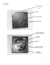
Orient the filter assembly so that the aperture slot is vertical and the motor is away from the
instrument housing. Mount the filter assembly or light source/detector to the desired slit housing
with (3) 8-32 screws.
B. Connecting Control Unit
Each control unit must be connected to an AC line of 115 vac. There is also a cable with a 15 pin
connector attached to each control unit which must be connected to the filter wheel assemblies. For
RS-232 operation of the filter assemblies, each control unit must be connected to separate RS-232
ports of a computer or terminal. Acton Research Corporation offers the following connecting cables:
CC-499-1 Cable for IBM-PC or XT compatible computers,
25 pin female connector to 9 pin male connector
CC-499-2 Cable for IBM-PC/AT or compatible computer,
9 pin female connector to 9 pin male connector
CC-499-3 Cable for computer terminal
25 pin male connector to 9 pin male connector
If none of the above cable assemblies are compatible with your computer or terminal, contact Acton
Research Corporation for a custom cable or one may be constructed using a standard DE-9P
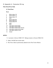
connector at the filter controller end with the following connections:
pin # description
1 open
2 RD received data to the computer
3 TD transmitted data from the computer
4 open
5 ground
6 open
7 RTS connect these two
8 CTS pins together
9 open
For the optional IEEE-488 operation, connect a standard IEEE cable between the two control units
and connect an additional IEEE cable from one control unit to the IEEE controller.
4