


3
8.8.
8.8.
III. INSTALLATION
CAUTION: Always turn the amplifier off when installing or removing the SPA-3.
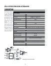
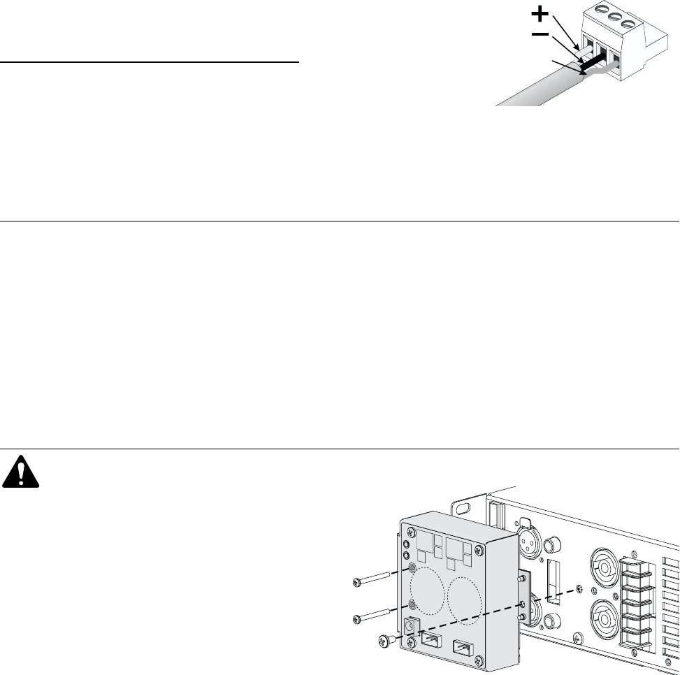
Connecting inputs
The signal wires attach to each “Euro-style” terminal block as
shown in the illustration at the top of this page. Pay attention to
signal polarity. Strip the wires approximately 0.35 inch (9 mm). The
screw head above each terminal opens and closes its clamp; after
inserting the wire in the terminal, tighten the clamp firmly.
If the input signal is unbalanced, use the + terminal for the signal
conductor and
both
the - and shield terminals for the shield.
The terminal blocks plug into their respective jacks on the SPA-3.
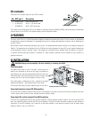
PowerLight 2 and two-channel CX, DCA amplifiers
Line up the SPA-3’s DataPort connector with the one on the amplifier’s rear panel. Press the SPA-3 onto the amplifier and secure
it to the chassis with the three screws included (see the illustration above).
PowerLight, ISA, and four-channel CX and DCA amplifiers
An SPA-3 will not physically mount on one of these amplifiers. A DPX-4 accessory bracket, however, can hold up to four SPA-3
units. Use a DataPort cable to connect the SPA-3 to the amplifier. The SPA-3 will draw the power it needs from the DataPort of
PowerLight, CX and DCA amplifiers, but if used with an ISA series amplifier, it will require an external 15-volt DC power supply
capable of 300 mA, such as a QSC DPX-1.
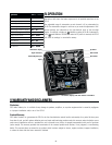
II. FEATURES
The heart of the SPA-3 is a Crystal Semiconductor digitally controlled dual-channel gain control. The user controls are pushbuttons
for adjusting the amount of attenuation, for bypassing (unity gain), for changing the adjustment increment, and for displaying the
firmware version.
Both channels feature electronically balanced input circuitry. The pseudo-balanced outputs connect to the amplifier through the
DataPort. The attenuation can be adjusted from 0 to 32 dB and can also be bypassed. A green LED for each channel indicates that
its pre-attenuation circuitry is passing a signal. The settings are non-volatile and are retained when the amplifier is turned off.
To improve common-mode noise rejection, an optional XF-1 input isolation transformer can be installed on each channel by a
qualified technician.
The screws are for mounting the SPA-3 to an amplifier or accessory bracket (see INSTALLATION), and the two plugs are detachable
terminal blocks for the SPA-3’s two balanced inputs (see the illustration above).
Kit contents
These parts are included along with your SPA-3 module:
ytQ#trapCSQnoitpircseD
200-731000-OCgulp"elyts-oruE"nip-3
2PP-181040-CSwercskcalb"8/11×04-4#
1PP-150080-CSwercskcalb"61/5×23-8#
shield
SPA-3 input connections
Attaching the SPA-3 to the amplifier