


- 8 -
POWER
ANT.
PA.SP.
+
EXT.SP.
_
21
34
Operation
(Continued)
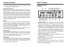
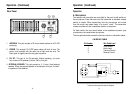
Rear Panel
1. ANTENNA: This jack accepts a 50 ohms coaxial cable with a PL-259
style plug.
2. POWER: This accepts 13.8 VDC power cable with built-in fuse. The
power cord provided with the radio has a black and red wire. The
black goes to negative and the red goes to positive.
3. PA. SP.: This jack is for PA operation. Before operating, you must
first connect a PA speaker (8 ohms, 4W) to this jack.
4. EXTERNAL SPEAKER: This jack accepts a 4 - 8 ohm, 5watt external
speaker. When the external speaker is connected to this jack, the built-
in speaker will be disabled.
- 9 -
Operation
(Continued)
Operation
A. Microphone
The receiver and transmitter are controlled by the push-to-talk switch on
the microphone. Press the switch and the transmitter is activated, release
switch to receive. When transmitting hold the microphone two inches
from the mouth and speak clearly in a normal “voice”. The transceiver
comes complete with low-impedance dynamic microphone.
For best results, the user should select a low-impedance dynamic type
microphone or a transistorized microphone.
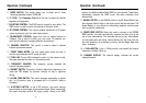
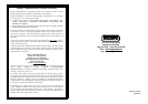
The microphone should provide the functions shown in schematic below.
4 WIRE MIC CABLE
Pin Number Mic Cable Lead
1 Audio Shield
2 Audio Lead
3 Transmit Control
4 Receive Control
Transceiver Microphone Schematic Diagram
3
2
1
4
TX
MI C