


English 3
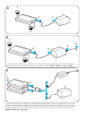
2. Plug the battery coupler cables into each of the battery DC input/output ports.
The battery coupler cables are marked with ‘1’ (primary) and ‘2’ (reserve) labels.
3. a. When charging two batteries, attach the power supply unit adapter to the DC
plug and connect the adapter to the the battery coupler.
b. When powering a device, connect the DC output cable of the device to the
end of the battery coupler. The primary battery supplies power to the
device and the reserve battery takes over when the primary battery is
disconnected or discharged.
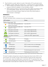
Indicators
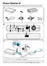
Refer to illustration B.
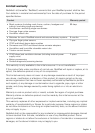
The RPS II provides LEDs to indicate its current operating state.
LED indicator Status
Battery charge level
1
(B-6)
One amber flashing (audible alert
beeps continuously)
Less than 5%
One green flashing (audible alert
beeps for 10 sec)
Less than 10%
One green continuous 10% to 40% (approximate)
Two green continuous 40% to 65% (approximate)
Three green continuous 65% to 90% (approximate)
Four green continuous Greater than 90% (approximate)
Charging (B-7)
Flashing green Charging
Constant green Fully charged
DC on/off (B-8)
Flashing blue RPS II turned on but not discharging
Constant blue RPS II turned on and discharging
Audible alert mute (B-5)
Flashing blue Not discharging and mute is active
Constant blue Discharging and mute is active
1
When setting the DC on/off switch, the charge level indicator may fluctuate between different levels.
To check the battery charge level, press the charge level check button (B-2) on the
control panel. The number of green LEDs indicates the approximate charge level.
To mute the alert, press the audible alert mute button (B-1). To permanently mute,
press and hold the audible alert mute button (B-1) for 5 seconds. To deactivate, press
the audible alert mute button (B-1) when the mute is still active.