


SERIAL FEATURES
XTENSYS INSTALLATION AND OPERATIONS MANUAL
29
Serial port usage (RS232)
The serial port on both the Xtensys switch (RJ12) and the User station (DB9) are used to update the unit’s firmware.
The following procedure for establishing a connection from your standalone computer or Notebook computer to the
Xtensys switch’s serial port or a User station uses Windows HyperTerminal™. Refer to your user’s manual if a
different communication program is being used.
To access an Xtensys serial port, the following items are required:
A serial cable (RJ12 connector and an appropriate adapter for the computer's serial port). The serial cable and
ada
pter are provided with each Xtensys switch (Rose part number KIT-ATRX). A standard DB9 null modem
cable can be used to flash user stations.
A dedicated computer, Notebook computer with a serial port, or a display terminal. Using a display terminal will
allow you to configure the Xtensys switch; however, you will not be able to upgrade new versions of firmware.
The computer or Notebook must not be attached to any Xtensys switches in the system being upgraded.
A communications program such as Windows HyperTerminal.
Connecting the Serial Cable
Attach the serial cable from the RS232 port on the Xtensys switch (RJ12 connector) to the COM1 port (DB9M) on
your computer. This COM1 port must be the same communication port your communication software is configured
for. If your communication software is configured for COM2 then connect the cable to this DB9M port.
Setting up Windows HyperTerminal
(The following instructions are using Windows HyperTerminal. The instructions may be different for other operating
systems or communication program)
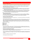
Start the Windows HyperTerminal program. The “New Connection” dialog box will display requesting a name for this
session. Enter a session name like “Xtensys serial option” and click ‘OK”. Next, the “Connect To” dialog box will
display. Click on the “Connect Using” down arrow to display the connect options. Select the COM 1 option, then
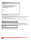
click “OK”. The COM1 properties dialog box will display. Using the drop-down selection boxes, select the following
values for each setting.
Bits per second 115200
Da
ta bits; 8
Parity; None
Stop bits; 1
Flow Control; None
Click “OK” when all values have been entered. The HyperTerminal dialog box will display and information can be
exchanged with the Xtensys switch properly. You can save this setup so the next time its needed, you can select the
ICON with the name you gave it and these settings will already be established.
Starting a serial communication session
Verify that “Connected” appears in the bottom left corner of the HyperTerminal window. If “Connected” is not present,
click on the “Call” icon. “Connected” should display in the bottom left corner.
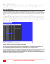
Power on or cycle power on the Xtensys switch and press the spacebar when the message, “Hit the spacebar within
1 second to get serial options menu” appears on your screen. The serial menu will appear after the diagnostic check
completes.
The serial menu enables you to perform flash upgrades.
Following explains the serial menu options: