


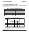
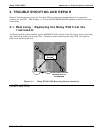
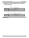
Relay PCA 04523 Addendum to E-Series Operator Manuals
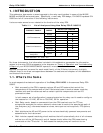
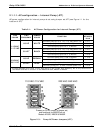
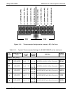
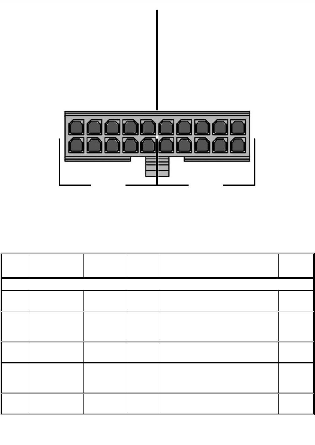
Input Gain Selector 1 – 11
Type J Compensation 4 – 14
Output Scale Selector 2 – 12
Type J Compensation 3 – 13
Termination Selector 5 – 15
TC1 TC2
Input Gain Selector 6 – 16
Type J Compensation 9 – 19
Output Scale Selector 7 – 17
Type J Compensation 8 – 18
Termination Selector 10 – 20
Figure 2-8: Thermocouple Configuration Jumper (JP5) Pin-Outs
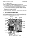
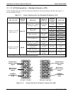
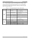
Table 2-5: Typical Thermocouple Settings for M100E/M200E series analyzers
TC
TYPE
TERMINATION
TYPE
OUTPUT
SCALE
TYPE
JUMPER
BETWEE
N PINS
USED ON
JUMPER
COLOR
INPUT TC1 (J15)
K
GROUNDED 5mV / °C
2 – 12
4 – 14
M100EH with Mini HiCon Converter
BROWN
K
ISOLATED 5mV / °C
2 – 12
4 – 14
5 – 15
M100EH with Mini HiCon Converter
GREY
K
ISOLATED 10mV / °C
4 – 14
5 – 15
M100E/M200E with Moly Converter
PURPLE
J
ISOLATED 10mV / °C
1 – 11
3 – 13
5 – 15
M100E/M200E with Moly Converter
RED
J
GROUNDED 10mV / °C
1 – 11
3 – 13
M100E/M200E with Moly Converter
GREEN
05118 Rev B3 13