


Circuit Board Configuration Jumpers
To change the jumper settings, remove the top cover.
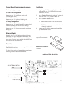
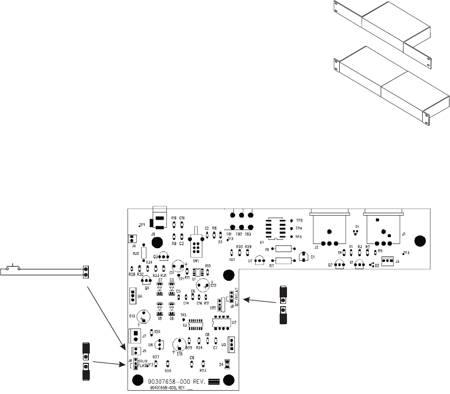
J6: Call Light Configuration
Jumper on pins 1-2: Light flashes during call
(default-typical setting).
Jumper on pins 2-3: Light stays lit during call.
J8: Relay Configuration
Jumper on pins 1-2: Normal Open (NO) contacts closed
continuously during call (default-typical setting).
Jumper on pins 2-3: Relay contacts toggle at flash rate
during call.
External Switch
Normally, the CIA-1000 indicator light and relay are
actuated by call signals on the intercom channel. The
CIA-1000 may also be modified to actuate the light and
relay using an external, user-supplied switch. See Figure
for location of the switch connector.
Mounting
The CIA-1000 can be wall mounted using the slotted holes
in the bottom of the case.
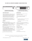
The front-light version can be installed in an equipment
rack using optional Audiocom rack mounts.
Installation
1. Plug the supplied PS-L Power Supply into an AC wall
outlet and into the
12-15 VDC
power jack on the
back of the CIA-1000.
2. Set the
System Select
switch to the "in" position for
Audiocom or the "out" position for RTS TW.
3. Set the
Channel Select
switch:
• Audiocom, the position of the switch does not
matter.
• RTS TW intercom system: select either channel 1
or channel 2 as desired.
4. Connect the CIA-1000 to an intercom channel like
any other intercom station.
2
602
Flash during call
On continuously during call
J5: EXTERNAL SWITCH
Toggle during call
On continuously during call
J8: RELAY OPERATION
J6: CALL LIGHT OPERATION
Location of Jumpers and External Switch Connector
RMK-S Single-Unit Rack Mount Kit
for one 1/2-rack wide Audiocom
component*
RMK-D Dual-Unit Rack Mount Kit
for two 1/2-rack wide Audiocom
components*
Audiocom Rack Mount Kits