


• Model 53799 Installation (Figure 1 & 2)
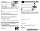
Step 1-Apply three complete wraps of PTFE tape to the threaded male ends of the valves.
Caution: Use only PTFE tape on threaded connections. Pipe dope and other types of pipe
thread sealants can damage plastic threads.
Step 2-Install a slip/thread adapter into threaded male end of the valve and tighten securely.
Step 3-Cut a 4" length of 1" schedule 40 PVC pipe for each valve.
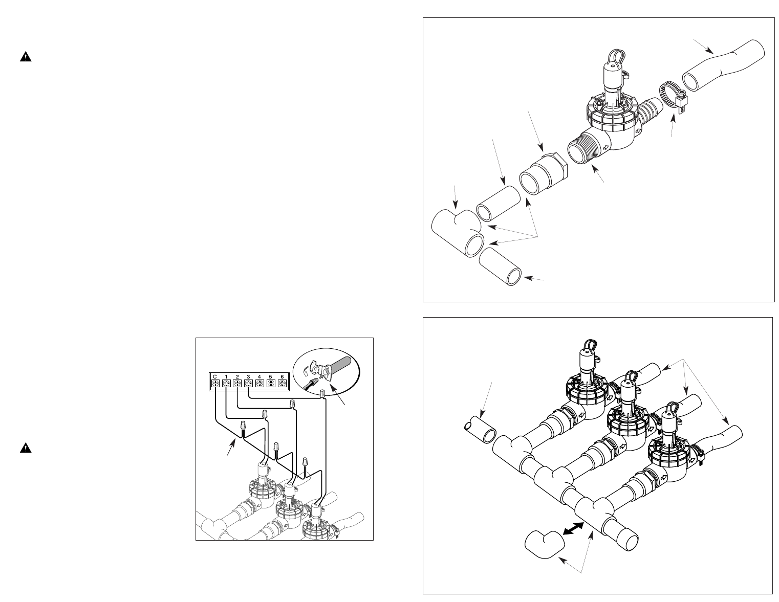
Step 4-Using PVC primer and cement, assemble the valve and PVC components as shown, aligning
the tee fitting perpendicular to the valve. Repeat this procedure for each valve in the manifold.
Note: The last valve in the manifold can be connected with a 90° elbow instead of a tee. However,
if future expansion of the sprinkler system is expected, use the tee fitting and a 4" section of 1"
schedule 40 PVC pipe capped on the end. This enables the main line to be easily connected to
additional downstream valves.
Step 5-Slip a stainless steel hose clamp onto the poly pipe. Push the poly pipe onto the valve’s
barbed fitting covering all barbs. Position the clamp over the barb contact area and tighten securely.
Step 6-Using 4" sections of 1" schedule 40 PVC pipe, connect the valve assemblies together to
create the manifold, making sure the valves are aligned during assembly.
Step 7-Ensure the end of the supply line is dry and free of burrs. Cement the manifold to
the main line.
Step 8-Allow the cemented connections to cure for a minimum of one hour (or per the cement
manufacturer’s directions) before applying water pressure. If no leaks occur after pressurization,
begin connecting the sprinkler zone piping using 1 1/4" poly pipe.
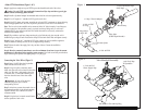
Connecting the Valve Wires (Figure 3)
Step 1-Route 18 AWG direct-burial sprinkler
cable from the timer to the valves.
Step 2-Using wire splice connectors, attach
either wire from each valve solenoid to the white
cable wire. This wire is designated as the valve
“Common Wire.” Connect the remaining wire
from the solenoid to one of the color-coded
wires.
Important: All wire splices must be
insulated with grease caps or similar
waterproofing devices.
Step 3-At the timer, connect the control wires to
the numbered terminals in the desired operating
sequence and the valve common wire to the
common terminal.
Step 4-Using the timer’s manual control feature,
test the operation of each valve.
Cement Joints
1" Slip x Thread Adapter
1" Slip x Slip x
Slip PVC Tee
Valve Inlet
(PTFE-Taped threads)
1" Sch 40 PVC
4" Long
Figure 2
Figure 1
90° Elbow or Tee and Cap Plug
1" Sch 40 PVC
Water Supply Pipe
Valve Manifold Assembly
1 1/4" Poly Pipe
To Sprinklers
1" Sch 40 PVC
Hose Clamp
1 1/4" Polyethylene Pipe
(Poly Pipe)
Figure 3
Timer Connection
Common Wire
Grease Cap
RELEASED Version ©Toro 2008-2008