


©2012 The Toro Company
Micro-Irrigation Business
1588 N. Marshall Avenue, El Cajon, CA 92020-1523, USA
Tel: +1(800) 333-8125 or +1(619) 562-2950
Fax: +1(800) 892-1822 or +1(619) 258-9973
toro.com
ALT057 1/04
600 Series Valves
Additional Features:
• Self-cleaning In-line filter for filtration
of the command system water
• Non-continuous metering system –
since only a small exchange of
control water is used to operate the
main valve, the system is less
susceptible to failure due to plugging
• Available in 2" and 3" (51 and 76mm)
• Working pressure is 10 to 150 psi
(.7 to 10.3 bar)
• Flow range from 80 gpm to 300 gpm
(5.0 to 18.9 l/s)
• Manual external bleed
• Glass reinforced nylon body and
bonnet give superior high
temperature strength
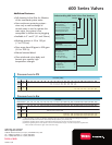
Understanding 600 Series Valves Part Numbers
Example: 601 –3–T– 01 –B
Valve Category
B
asic Hydraulic –600
P
ressure Reducing –601
P
ressure Sustaining/Relief –602
P
ressure Reducing and –603
S
ustaining/Relief Valve
Valve Size
T
wo-inch Valve –2
Three-inch Valve –3
Options
Three Position Selector Valve –T
Electric Control
N
o Solenoid –00
Solenoid 24VAC –01
24 VDC Latching –02
9 – 12 VDC Latching –03
Pilot Springs
5–20psi Blue –B
9–35psi Green –G
21–113psi Silver –S
Pressure Loss in PSI
Flow Rate (GPM)
Style Size 10 20 30 40 50 60 70 80 90 100 110 120 130 140 150 175 200 225 250 275 300
Globe
2"
2.1 2.7 3.3 4.0 4.8 5.6 6.5 7.5
Angle 1.2 1.6 2.0 2.4 2.8 3.3 3.9 4.4
Globe
3"
2.5 3.0 4.1 5.3 6.7 8.3 10.1
Angle 1.9 2.4 3.3 4.3 5.5 6.9 8.5
Pressure Loss in Bar
Flow Rate
Liters/second 0,5 1,0 1,5 2,0 3,0 4,0 5,0 6,0 7,0 8,0 9,0 10,0 11,0 12,0 13,0 14,0 15,0 16,0 17,0 18,0 19,0
M
3
/Hour 1,8 3,6 5,4 7,2 10,8 14,4 18,0 21,6 25,2 28,8 32,4 36,0 39,6 43,2 46,8 50,4 54,0 57,6 61,2 64,8 68,4
Style Size
Globe
50mm
0,14 0,21 0,28 0,37 0,47
Angle 0,08 0,12 0,17 0,22 0,28
Globe
75mm
0,18 0,21 0,25 0,30 0,35 0,41 0,48 0,54 0,62 0,70
Angle 0,14 0,16 0,20 0,24 0,29 0,34 0,39 0,45 0,52 0,59
NOTES: (1) When designing a system, the industry standard for flow rate velocity through pipes and fittings is 5 Fps (2m/s).
(2) Pressure loss data is derived from valves independently tested by C.I.T., Fresno, CA.
(3) Hydraulic actuated valves vented to atmosphere will show lower pressure loss figures at low flows.
(4) Pressure regulating valves must operate in the recommended flow ranges – For the best pressure regulation the
valves should be sized at the upper end of the flow range.