


r
~
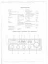
1. MICROPHONE CONNECTOR: Receptacle for microphone connection.
2. ON/OFF-VOLUME: Turn power on to radio and allows adjustment to the
desired listening level with clockwise rotation.
3. SQUELCH/PA SWITCH: Used to quiet background noise when no signal is being
received. Proper adjustment is such that the control is advanced only siightly
beyond the point where the background noise is marginally quieted. To make
PA (Public Address), rotate the switch fully counter clockwise then, PA function
is available.
4. RF GAIN: This control is used primarily to optimize reception in strong signal
areas. Gain is reduced by counter clockwise rotation of the control.
5. MIC GAIN: The control is used to adjust as required, microphone input sensi-
tivity for optimum amount of modulation in transmit. Uniden marine trans-
ceivers have been designed to permit the user to attain levels of modulation up
to 100% depending on the setting of the microphone gain control, using the
microphone provided with the unit. Uniden's automatic compression and peak
limiting circuits assure maximum modulation with minimum distortion.
6. CHANNEL SELECTION CONTROL: This control selects the desired channel
for transmission and reception. All channels except channel 88, may be used for
communications between stations. Channel 88 has been reserved by the D.O.C.
for emergency communications involving the immediate safety of individuals or
immediate protection of property. This is as D.O.C. rule and applies to all
operators of citizens band radios. .
7. CB/WX SWITCH: This switch selects different operating modes. In the CB
position, WX receive function is disabled. At the WX position, CB and AN L
Functions are disabled.
8. WX1-WX2/ANL-ON OFF SWITCH: In the WX position of CB/WX SWITCH,
you can select WXl or WX2 by this switch. And when it is in CB Mode, this
switch operates as ANL ON/OFF Switch.
9. CHANNEL 88 ON OFF SWITCH: In CB Mode this switch selects channel 88,
Channel Indication will disappear and CH 88 LED will be on.
10. RF POWER/ 's" METER: This meter shows the Radio Frequency power when
transmitting and the strength of the incoming signal when receiving. A change of
one "S" unit indicates a change of 6 dB in signal level. The metering circuit is
calibrated so that for 100 microvolts, the "S" meter will read S-9.
11. CHANNEL INDICATOR: Light Emitting Diode (LED) indicates the channel
number in use.
12. TX INDICATOR: Light Emitting Diode (LED) indicates red while transmitting.
-5-
======r::
...-..-..-......-------.
}
r
f
---