


Permanent Installation
The permanent installation of the inverter and the required wiring and safety devices to the 12 Volt DC power
source must be performed by a professional installer. Further requirements are:
1. The inverter is supplied with 4 Special Crimp Connectors to connect the power source wiring to the inverter
DC input terminals. They are designed to be crimped onto #2AWG copper conductor cables (not supplied).
2. The #2AWG power source cables must not exceed 6 feet in length.
3. A 300 Amp ANL Fuse (not supplied) installed in the proper Fuse Holder (not supplied) must be connected in-
line as part of the positive power source input cable as close as possible to the power source connections.
4. A #12AWG insulated wire should be connected between the Grounding Terminal on the inverter (see
“Controls and Functions”, “Back View Diagram” on page 4 ) and the ground terminal on the appliance (such
as a TV or Radio) to minimize electrical noise and reception interference.
CAUTION: Do not connect this wire to the inverter’s Negative (Black, -) DC input terminals.
CAUTION: Violation of these requirements may result in unsafe operation and/or equipment failure. Damage
to the inverter as a result of improper installation voids the warranty.
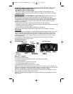
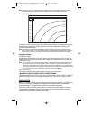
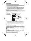
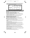
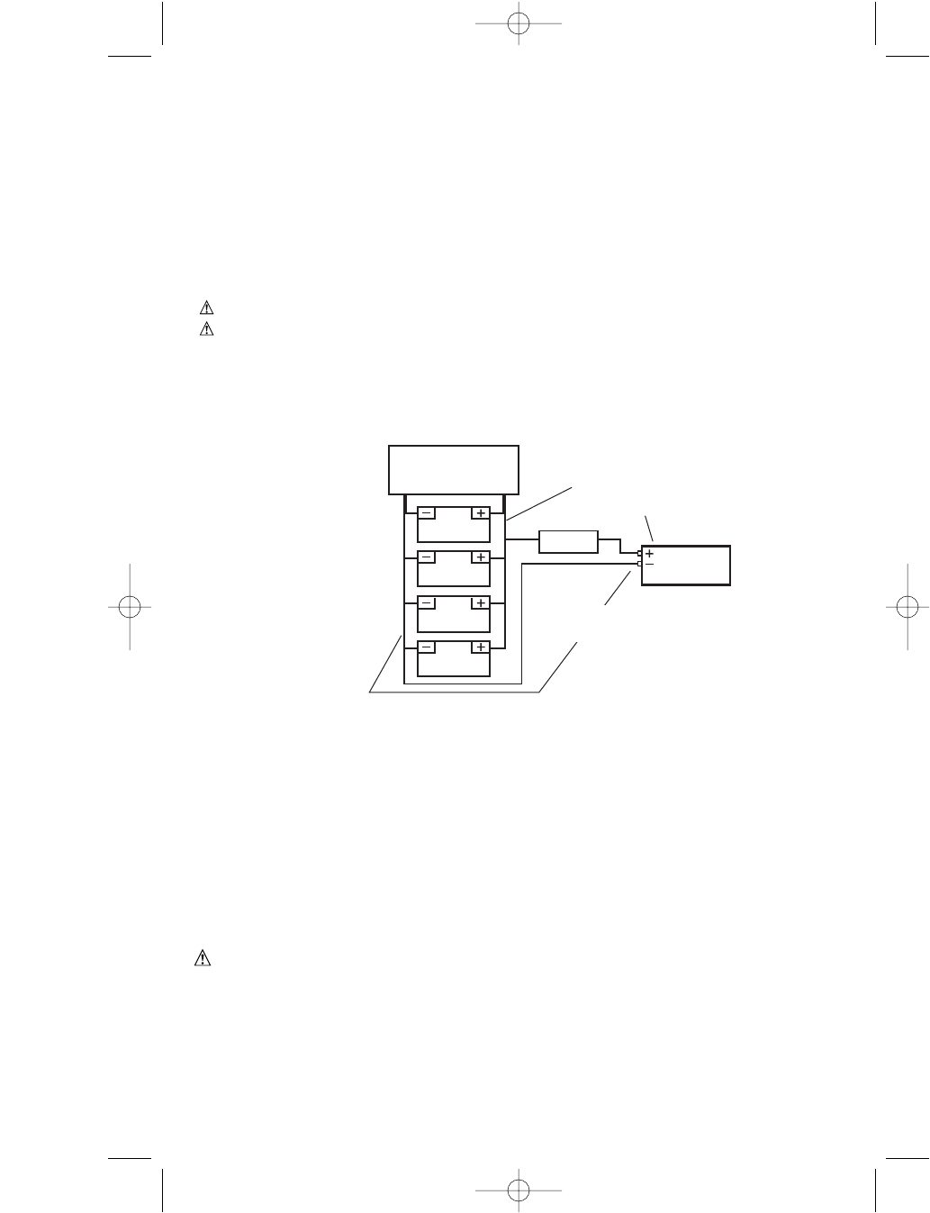
The DC power source must be a well-regulated DC power supply as typically found in vehicle and deep-cycle
marine batteries. The DC power source may also be two 12 volt batteries connected in parallel. On larger
applications the power source may be several batteries connected in parallel as shown in the following
“Permanent Battery Configuration” diagram.
Note: For typical heavy-duty uses in a Permanent Installation, an ANL fuse must be added as close as possible to
the power source (battery) positive terminal. The fuse amperage size must be appropriate to allow
simultaneous operation of all the AC appliances to be powered, with delay characteristics that allow for the
momentary high start-up current requirements of inductive loads. Use the specified fuse block (fuse
holder) and fuse. For full rated output and motor start-up surge output, ensure that the installation is
configured to handle the full load. See the “Permanent Installation” section of this Instruction Manual.
Connection To Load
The Power Inverter is equipped with standard North American three-prong type outlets. Plug the cord from the
equipment you wish to operate into the AC outlet(s). Make sure the combined load requirement of your
equipment does not exceed maximum continuous power.
The Power Inverter is engineered to be connected directly to standard electrical and electronic equipment in the
manner described above. Do not connect the Power Inverter to household or RV AC distribution wiring. Do not
connect the Power Inverter to any AC load circuit in which the neutral conductor is connected to ground (earth)
or to the negative of the DC (battery) source.
WARNING: TO REDUCE THE RISK OF ELECTRIC SHOCK, PROPERTY DAMAGE OR PERSONAL INJURY:
Never connect unit directly to AC distribution wiring.
Operating Tips
For best operating results, the inverter should be placed on a stable, flat surface. The inverter should only be
used in locations that meet the following criteria:
DRY — Do not allow water or other liquids to come into contact with the inverter.
COOL — Surrounding air temperature should be between –0°C and 40°C — ideally between 15°C and 25°C
(60-80°F). Keep the inverter away from direct sunlight, when possible.
BATTERY CHARGING
FROM COMMERCIAL
AC, ENGINE, SOLAR, ETC.
BATTERY
BATTERY
BATTERY
BATTERY
(MAX FEET OF
AWG WIRE)
(See the “Specifications” section)
ANL FUSE
FUSE HOLDER
(MAX FEET OF
AWG WIRE)
(See the “Specifications” section)
FUSE TO BATTERY LENGTH
+ FUSE TO INVERTER LENGTH
MAXX SST™
POWER
INVERTER
Permanent Battery
Configuration Diagram
9
90548011 VEC054D INVERTER.qxp 3/6/09 10:41 AM Page 9