


7.08
0.29
0.29
10.725
11.23
3.70
1.810
3.625
5.615
1.85
0.36 Typ.
3.25
3.625
3.54
3.70
1.81
0.36
1.85
0.25
(4) 6-32
Clinch Nuts
0.08
0.203 Dia.
4 Places
S
S
p
p
e
e
c
c
i
i
f
f
i
i
c
c
a
a
t
t
i
i
o
o
n
n
s
s
8.0
5.87
7.10
1.60
11.25
(4) .43 Dia.
T
E
L
E
P
H
O
N
E
9.375
12.6
7.45
7.10
3.55
1.25
7.10
1.625
0.875
3.55
Center Line
Center Line
3/4" Conduit
Knockout
3/4" Conduit
Knockout
7.08
5.48
11.23
3.30
2.50
4.40
1.65
1.25
1.25
2.74
2.50
1.25
0.80
Typ.
(2) 8-32
Clinch Nuts
0.203 Dia.
4 Places
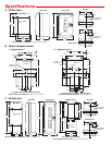
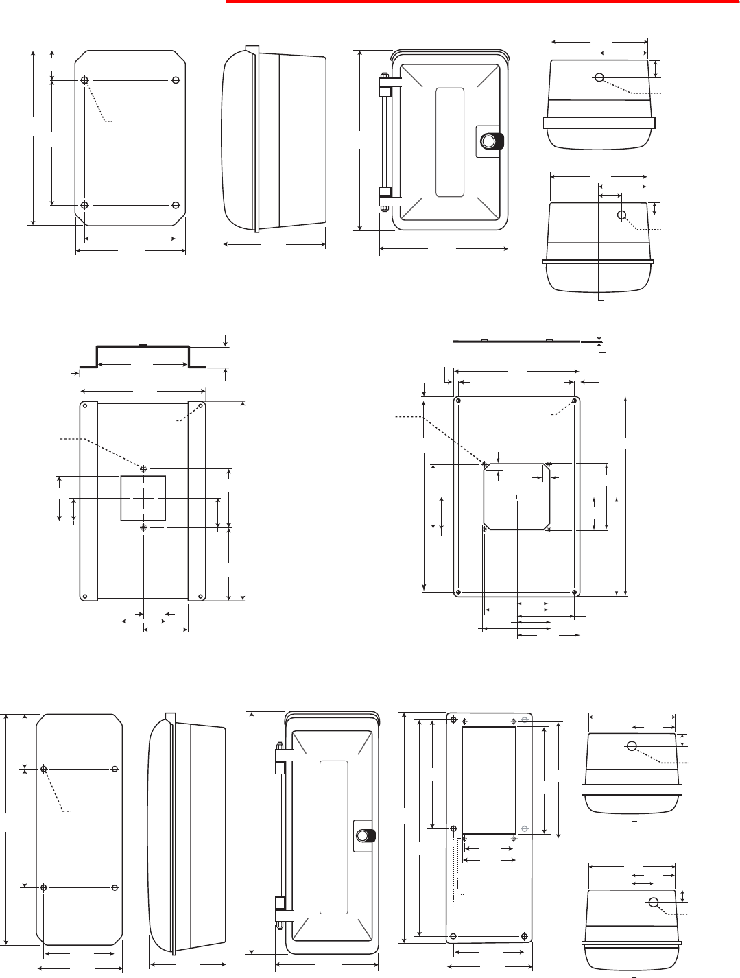
A. VE-9x12 Box
Rear View
Side View
Front View
1. Adapter Panel 1
2. Adapter Panel 2
B. VE-9x12 Adapter Panels
8.0
5.88
5.0
19.0
(4) .43 Dia.
T
E
L
E
P
H
O
N
E
9.25
20.25
7.25
7.19
6.49
9.14
18.76
(4) Tapped 6-32
(6) 0.218 Diameter
7.02
18.28
9.50
9.00
4.50
4.60
7.02
3.51
0.75
Center Line
3/4" Conduit
Knockout
7.02
1.75
3.51
Center Line
3/4" Conduit
Knockout
0.75
C. VE-9x20 Box
Rear View
Side View
Front View
Adapter Panel
Minimum Internal Clearance: 5.75” x 10.0” x 6.75”
(12 gauge Aluminum Black Powder Paint)
Minimum Internal Clearance: 5.75” x 10.0” x 5.25”
(12 gauge Aluminum Black Powder Paint)
Minimum Internal Clearance: 5.75” x 10.0” x 4.0”
Minimum Internal Clearance: 5.75” x 17.25” x 6.75”
(14 gauge Stainless Steel)
Minimum Internal Clearance: 5.75” x 17.25” x 4.0”
Top View
Bottom View
Top View
Bottom View