


4
NOTE: Underwriters Laboratories (UL) does not require all fixtures to have ground wires. These
fixtures meet all UL specifications.
1. Turn off power at circuit box to avoid possible electric shock.
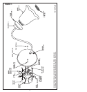
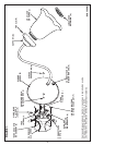
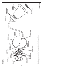
2. Remove cap nuts (A) from back plate (B) and remove universal mounting plate or cross bar
(C), leaving mounting screws (D) in place (see fig. 1).
3. Secure universal mounting plate or cross bar (C) to outlet box (E) with outlet box screws (F)
(not included).
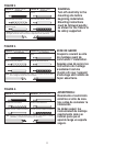
4. Identify color coding of fixture wires (see fig. 2 on page 11).
5. To connect wires, take black fixture wire (group A from fig. 2) and place evenly against
black outlet box wire. Do not twist wires.
6. Fit wire connector (G from fig. 1) over wires and twist until there is a firm connection. If
wire connector (G) easily comes off, reattach and check again for a firm connection.
7. Repeat steps 5 and 6 with the white (group B from fig. 2) fixture and outlet box wires.
8. Partially thread green grounding screw (H) into side hole (I) on universal mounting plate or
cross bar (C) (see fig.1).
9. Wrap ground wire from fixture and ground wire (metal or green wire) from outlet box (E)
around green grounding screw (H) on universal mounting plate or cross bar (C).
10. Tighten green grounding screw (H). Do not over tighten.
11. Tuckwires inside outlet box (E) (see fig. 1).
MOUNTING AND WIRING INSTRUCTIONS
FIXTURE ASSEMBLY INSTRUCTIONS
Warning: This fixture is for indoor use only.
1. Position back plate (B) over mounting screws (D) by aligning back plate openings (J) with
mounting screws (D).
NOTE: Position back plate with power switch (K) pointed downward.
2. Secure with cap nuts (A).
3. Install glass shade(s) (L) into holder(s) (M). Secure with thumb screws (N) or retaining
ring(s) (O), whichever is applicable.
4. Install lamp(s). Do not exceed recommended wattage.
5. Turn power back on at circuit box.