


OPERATING PRINCIPALS
21
20
OPERATION
For You Technical Types.
1. Basic Operating Principles:
Whistler inverters work in two stages. During the first stage,
the DC to DC converter increases the DC input voltage from
the power source (e.g. a 12 volt battery) to 145 volts DC. In
the second stage, the high voltage DC is converted to 110
volts (60 Hz AC) using advanced power MOSFET transistors
in a full bridge configuration. The result is excellent overload
capability and the capacity to operate difficult reactive loads.
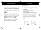
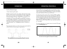
The output waveform resulting from these conversions is a
"quasi-sine wave" or a "modified sine wave" as shown on
below.
This stepped waveform is similar to the power generated by
utilities and has a broad range of applications.
The modified sine wave produced by the Inverter
The modified sine wave produced by your Whistler inverter
has a root mean square (RMS) voltage of 110 volts. The majority
of AC voltmeters measure RMS voltage and assume that the
measured waveform will be a pure sine wave.
Consequently, these meters will not read the RMS modified
sine wave voltage correctly and, when measuring your Whistler
inverter output, the meters will read about 20 to 30 volts too
low. To accurately measure the output voltage of your inverter,
use a true RMS reading voltmeter such as a Fluke 87, Fluke
8060A, Beckman 4410, Triplett 4200 or any multimeter identified
as "True RMS."
For more information on inverters see our Inverter FAQ page
at www.whistlergroup.com
A true sine wave typical of home AC outlet.
pro1200to3000w.qxp 4/30/2010 8:55 AM Page 23