


3
INSTALLATION (cont’d)
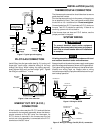
PILOT GAS CONNECTION
Install fitting into pilot gas outlet (see fig. 2), turning until
finger-tight. Insert clean, deburred tubing all the way
through the fitting. While holding the tubing securely,
slowly tighten fitting until you feel a slight "give". Tighten
the fitting an additional 1
1
⁄2 turns.
ENERGY CUT OFF (E.C.O.)
CONNECTION
A five-function valve uses the 2 E.C.O. terminals that are
connected to the magnetic assembly where the thermo-
couple connects to the 36C valve line interrupter. An
E.C.O. device is mounted in the furnace near the limit
control and a lead assembly is connected to the E.C.O.
terminals on the 36C valve.
NOTE
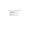
Pilot Gas
Outlet
Gas Outlet
PRESS
TAP
PILOT
Figure 3. Gas valve side view
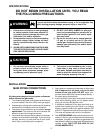
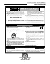
Horizontal
Drop
Piped Gas
Supply
Gas Valve
3 in.
minimum
Gas Valve
Riser
Piped Gas
Supply
3 in.
minimum
Drop
Horizontal
Riser
Gas Valve
Tubing Gas
Supply
3 in.
minimum
NOTE:
Always Include
A Drip Leg In Piping
Figure 2. Typical gas valve piping
All wiring should be installed in accordance with local
and national electrical codes and ordinances.
Always check that the electrical power supply used agrees
with the voltage and frequency shown on the gas control.
The typical wiring diagram shows only the terminal iden-
tification and wiring hook up. Always refer to wiring
instructions provided by Equipment Manufacturer for sys-
tem hookup operation.
THERMOCOUPLE CONNECTION
The thermocouple connection should be clean to ensure
good electrical contact.
Run the thermocouple nut into the power unit tapping as
far as possible by hand. Then use a small wrench to set
the nut with a
1
⁄4 to
1
⁄2 additional turn. Do not overtighten.
Connect leads from E.C.O. terminals to E.C.O. device on
furnace. Test E.C.O. device for continuity. If there is no
continuity, power unit will not hold in.
If the furnace does not have an E.C.O. device, use the
jumper provided in the pack.
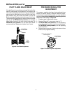
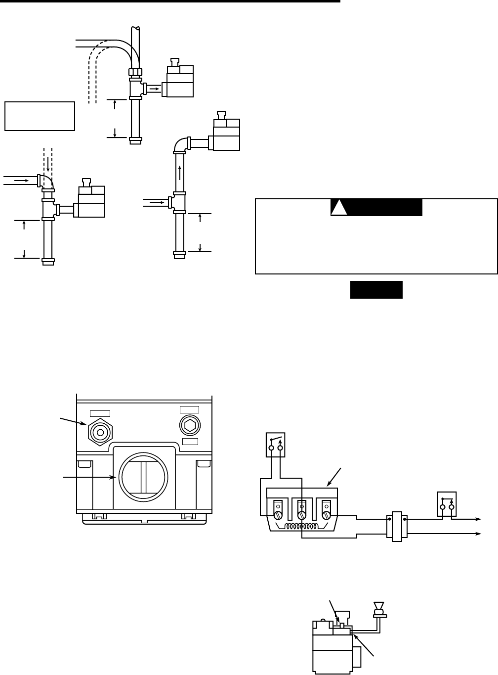
GAS VALVE
TERMINAL PANEL
Figure 4. Wiring for 36C53
TH TH-TR TR
LINE
HIGH
LIMIT
24 VAC
HOT
TRANSFORMER
THERMOSTAT
SYSTEM WIRING
To prevent electrical shock and/or equipment
damage, disconnect electrical power to system at
main fuse or circuit breaker box until installation
is complete.
CAUTION
!
THERMOCOUPLE
CONNECTION E.C.O.
DEVICE
LEAD
ASSEMBLY
E.C.O. TERMINALS
Figure 5. Wiring for Energy Cut-Off (E.C.O.) connection