


4
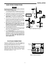
SYSTEM WIRING
REFER TO AND FOLLOW THE APPLIANCE
MANUFACTURER’S WIRING DIAGRAM. REFER TO
FIG. 4 FOR TERMINAL IDENTIFICATION.
INSTALLATION (con’t)
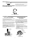
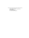
Pilot Adjust
Cover Screw
Gasket
Pilot
Adjust
Screw
Figure 5. Pilot flame adjustment
NOTE
PILOT FLAME ADJUSTMENT
This control was factory preset and will not normally
require additional adjustment of pilot flame.
If the pilot flame is low and does not engulf the bulb of the
mercury flame sensor, the system will not energize the
main valve.
If pilot gas pressure is too high, gas will sputter past the
ignition electrode, and may not ignite. High pilot gas
pressure may also cause the flame to lift off the burner,
causing the flame sensor bulb to sense “low” heat.
To adjust the pilot flame, remove the pilot adjust cover
screw and gasket (see fig. 6) to expose adjusting screw.
To REDUCE pilot flame, turn the pilot adjust screw
clockwise. To INCREASE pilot flame, turn the pilot
adjust screw counterclockwise. Replace and tighten cover
screw and gasket.
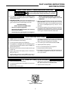
Figure 4. Typical gas valve wiring
Redundant
Valve Coil
(Pilot Valve)
Main Valve
12
34
ADJUSTMENT
All wiring should be installed in accordance with local and
national electrical codes and ordinances.
Check that the electrical power supply used agrees with
the voltage and frequency shown on the gas control.
PRESSURE REGULATOR
ADJUSTMENT
The pressure regulator has been factory adjusted for
3.5” W.C. (Natural Gas, full flow) or 11.0” W.C. (LP Gas,
full flow). Although additional adjustments will not nor-
mally be necessary, the regulator may be adjusted if
required. Do not force the adjusting screw beyond the
limits that it can easily be adjusted.
1. Attach a manometer to the outlet pressure tap of the
valve.
2. Energize valve to ignite main burner.
3. Remove “Reg. Adj.” cover screw (see fig. 6).
4. To DECREASE outlet pressure, turn the adjusting
screw (beneath the cover screw) counterclockwise.
To INCREASE outlet pressure, turn the adjusting
screw clockwise.
5. Replace the cover screw. Cycle the valve two or three
times to verify regulator setting.
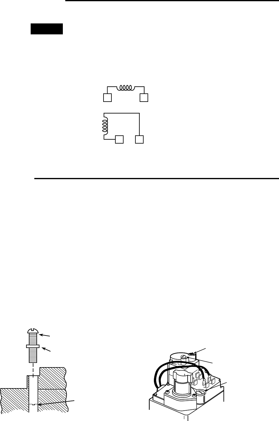
OFF
ON
NATURAL-LP
GAS SELECTOR
PILOT ADJUST
COVER SCREW
REGULATOR
COVER SCREW
Figure 6. Gas valve top