Page 5
GREY Wire: Negative Inhibit Input 1
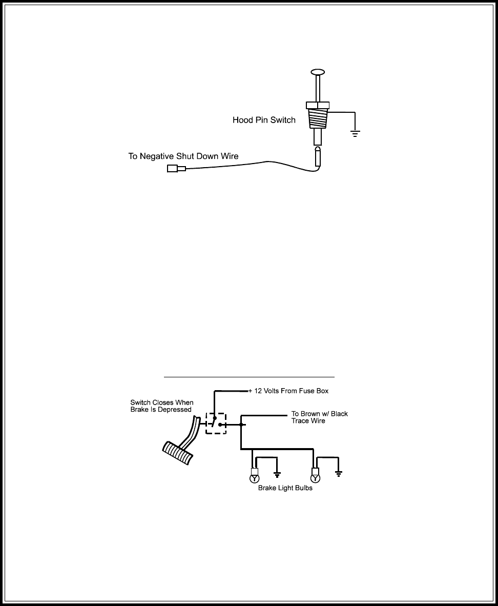
Connect the GREY wire to the previously mounted hood pin switch provided . This wire will be routed through the fire wall
into the engine compartment. It is necessary to use an existing grommet when passing wires through the fire wall to prevent
short circuiting. This is an important safety feature of APS 675, and failure to use this feature can result in serious injury.
Route the wire to the pin switch and connect it using the bullet connector provided.
GREY w/ BLACK Tracer Wire: Negative Inhibit Input 2
Any time the grey w/ black tracer wire is grounded, the Remote Starter will stop operating, even if the signal is received
from the transmitter.
If the brake light switch in the vehicle switches ground to the brake light circuit, connect the Grey w/ Black trace wire to
the output of the brake light switch. If the brake light switch in the vehicle switches +12 Volts, do not use the Grey w/ Black
wire; see Brown w/ Black tracer wire.
BROWN Wire: Positive Inhibit Input 1
Any time + 12 Volts is applied to the Brown wire, the Remote Starter will stop operating, even if the signal is received from
the transmitter.
If the vehicle has a factory installed hood pin switch, and that switch provides + 12 Volts to an under hood light, the Brown
wire can be connected to the existing pin switch.
BROWN w/ BLACK Tracer Wire: Positive Inhibit Input 2
Any time + 12 Volts is applied to the Brown w/ Black tracer wire, the Remote Starter will stop operating, even if the signal
is received from the transmitter. If the brake light switch in the vehicle switches + 12 Volts to the brake light circuit, connect
the Brown w/ Black trace wire to the output of the brake light switch. If the brake light switch in the vehicle switches ground,
do not use the Brown w/ Black wire; see Grey w/ Black tracer wire.
Brake Switch Positive Shutdown Detail
YELLOW w/ BLACK Tracer Wire: + 12 Volt Alarm By - Pass Output
NOTE: YOU MUST DISCONNECT THE IGNITION INPUT OF THE ALARM FROM ANY OTHER WIRE THAT
IT IS PRESENTLY CONNECTED TO IN THE VEHICLE.
This wire provides a + 12 Volt output when the ignition key is turned to the “ON” position, and 0 Volts when the ignition
key is “OFF” and when the vehicle is running under the control of the remote starter.
This wire should be connected to the ignition input of the alarm system.
The Yellow w/ Black wire output will allow you to remote start the vehicle while leaving the alarm armed, and to lock/unlock
the doors while running under control of the remote start unit.


