Installation Instructions CMS440N / CMS445N
5
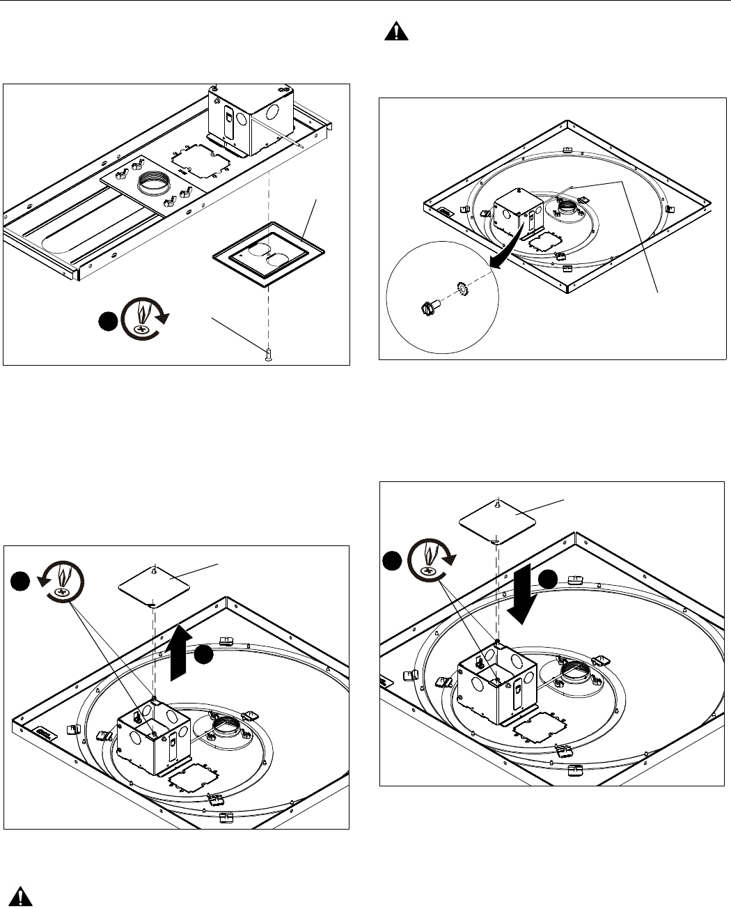
8. Attach face plate (A) using one 6-32 x 1/2" Phillips flat head
screw (B) after the CMS440N has been installed. (See
Figure 5)
Figure 5
CMS445N
1. Install a 15 Amp duplex outlet (not included) into the
electrical box.
2. Loosen two Phillips head screws on the electrical box.
3. Remove electrical box cover. (See Figure 6)
Figure 6
WARNING: IMPROPER WIRING CAN LEAD TO DEATH
OR SEVERE PERSONAL INJURY! Grounding must be
installed by qualified personnel using a UL Recognized No.
12AWG Green grounding wire connected to grounding lug on
box.
WARNING: ELECTRICAL SHOCK HAZARD! Turn off
power to device before performing service.
Figure 7
4. Wire the CMS445N as required.
5. Replace the electrical box cover. (See Figure 8)
6. Tighten two Phillips head screws in electrical box cover.
Figure 8
8
(B) x 1
(A)
2
x 2
Electrical box
cover
3
Grounding Lug Location
Green Grounding
Wire
6
x 2
Electrical box
cover
5


