SW6 VGA Audio • Installation and Operation
Installation and Operartion, cont’d
2-8
SW6 VGA Audio • Installation and Operation
2-9
Operation
Controls and indicators
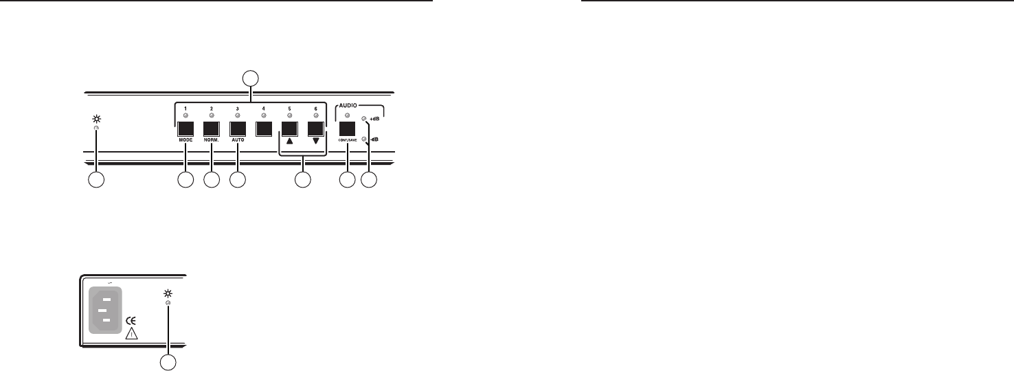
Figure 2-8 — SW6 VGA Audio front panel features
a
Power LED — Indicates that AC power is applied (also on the
rear panel, figure 2-9).
Figure 2-9 — Rear panel power connector
b
Input Buttons and LEDs — When the auto switch mode is off,
these buttons select the input. The LED for the selected input
lights.
The LEDs continue to indicate the selected input when the auto
switch mode is on. If no input LED is lit, no input has active
sync pulses and no input is selected.
N
Front panel input selection cannot be performed when the
auto switch mode is on.
c
Mode button — Use this button, with either the Auto or the
Normal button, to manually turn auto switch mode on or off.
This button is a secondary function of the Input 1 button.
d
Normal button — Use this button, with the Mode button, to
manually turn auto switch mode off. This button is a secondary
function of the Input 2 button.
e
Auto button — Use this button, with the Mode button, to
manually turn auto switch mode on.
Auto is a secondary function of the Input 3 button.
f
>
and
<
buttons — Use these buttons to increase or decrease
the selected input's audio gain or attenuation. These buttons are
secondary functions of the Input 5 and Input 6 buttons.
g
Audio Configuration/Save button and LED — Selects the
audio mode, in which you can set the input audio (gain and
attenuation level for each input.
h
+dB and -dB LEDs — Indicate polarity (gain [+] or
attenuation [-]) of input audio level setting.


