tracer2000 Network DVR Hardware User’s Manual
Version 3.1 Page 10 of 31
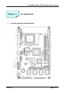
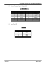
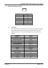
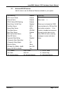
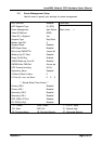
1.1 Power Switch for ATX Power Supply (JP1)
Signals JP1
Power ON/OFF 1-3
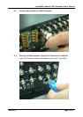
1.2 Reset / LED / Speaker (JP1)
Signals JP1
Power LED, Pin9+, Pin10- 9-10
External Speaker 14-20
HDD LED, Pin8+, Pin7- 7-8
System Reset Switch 5-6
SUSLED Pin4+, Pin2- 2-4
P.S. For the AT system (short Pin10 & Pin12) for power on.
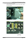
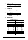
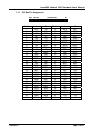
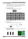
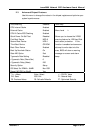
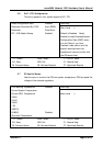
1.3 Internal USB Connector (USB2)
Signals USB2-1 USB2-2
Power 1 10
Data- 3 8
Data+ 5 6
USB GND 7 4
CHS GND 9 2
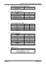
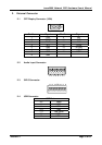
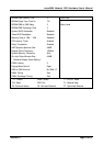
1.4 Power Connector (P1)
Signals P1
+12V 10
+5V 4, 6, 19, 20
-12V 12
-5V 18
+3.3V 1, 2, 11
5VSB 9
PS-ON 14
POWER-OK 8
Ground 3, 5, 7, 13, 15, 16, 17
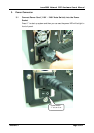
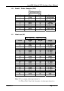
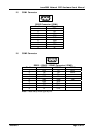
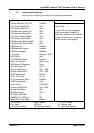
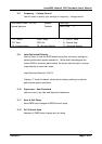
1.5 CMOS Clear (J1)
J1
POWER OFF and Move JUMPER from Pin1-2 to Pin2-3 of J1,
Reminding POWER OFF 1 Minute.
The Move JUMPER Back to 1-2 of J1