3-6 109627_0910
Range Forward Reverse
Low . . . . 0 - 6 mph (0 - 9.7kph) . . . . 0 - 4 mph (0 - 6.3kph)
High. . . 0-15.2 mph (0-24.5kph) . . 0 - 9.9 mph (0 - 15.8kph)
When the lever is placed in the outer slot, the tractor
will run in Locked AWD mode. When the lever is in
this position, the rear axle drive is activated for
improved traction in adverse conditions.
NOTE: When mower is in Locked AWD mode, only
low range is engaged.
WARNING: When driving on slopes, always oper-
ate in the Locked AWD mode.
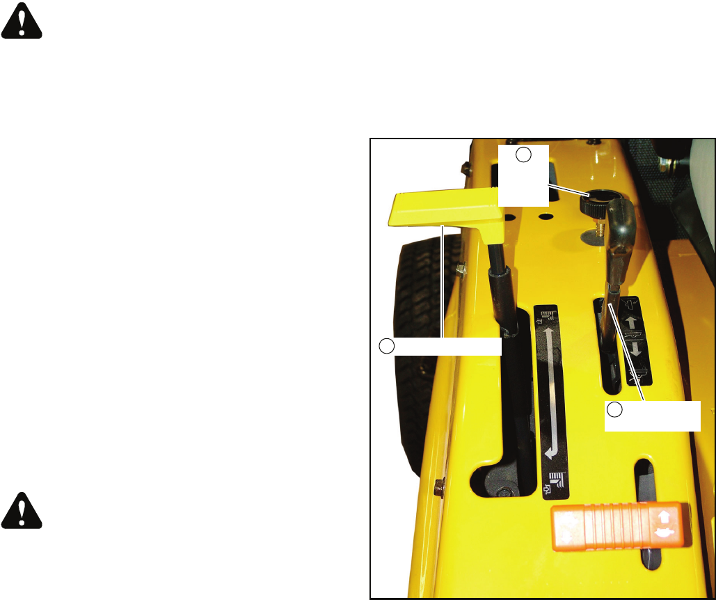
H. PTO Control lever (Figure 3-11) — This lever
engages and disengages the PTO. Move the lever
forward and hold it to engage the PTO. Move the lever
rearward to disengage the PTO.
a. PTO must be in disengaged position to start the
engine ( See “PTO stop system:” on page3-7).
IMPORTANT: Do not repeatedly engage and dis-
engage the PTO when Mower becomes clogged.
Doing so may cause PTO clutch failure. If Mower
becomes clogged, stop the engine, remove starter
key and clean underside of deck using a probe, not
your hand.
IMPORTANT: When PTO lever is engaged and
operator raises the front attachment, if attachment
is raised all the way up, the PTO will automatically
be disengaged. This is a tractor safety feature!
I. Tool Bar Lift Control lever (Figure 3-11) — The
front mounted equipment can be raised and lowered by
the tool bar lift control lever. Place handle in the
forward position to lower and to the rearward position
to raise front mounted equipment.
To lower and float the equipment, push the lever
forward. To raise the equipment, pull the lever
rearward and hold it until the equipment is raised to the
desired position.
WARNING: To avoid personal injury, disengage
the PTO Control lever before operating the Tool Bar
Lift Control lever.
J. Weight Transfer Control (Figure 3-11) — This
feature enables the operator to transfer the weight of
the deck or other equipment to the tractor unit.
Turn the knob clockwise, the effort of weight transfer
is increased, refer to the Weight Transfer Valve section
for additional information.
Seat adjustment
The seat can be adjusted four different ways to obtain the
most comfortable position:
1. Back angle (Figure 3-12)
2. Forward and rearward travel (Figure 3-13)
3. Weight (Figure 3-13)
4. Lumbar (Figure 3-14)
Steering wheel adjustment
The 3500/3700 is equipped with an adjustable steering
wheel which can telescope and tilt.
To telescope the wheel, turn the wheel hub to the left and
raise or lower the steering wheel to the desired height. Then
turn the hub to the right to lock it into position. (Figure 3-15)
NOTE: When locking the hub into position, do not
overtighten.
To tilt the wheel, pull up on the lever and move the steering
wheel fore or aft the desired position. If the wheel is not held
in position when the lever is raised, the steering wheel will
spring to its most forward position. Use this feature to gain
additional clearance when mounting and dismounting the
tractor. (Figure 3-16)
Safety start interlock system
The tractor is equipped with a safety start interlock system
consisting of the brake switch, seat switch, PTO switch and
transmission neutral switch.
Check tractor safety start interlock system daily, prior
to operation. This system is an important tractor safety
feature. It should be repaired immediately if it malfunctions.
The machine incorporates a separate seat switch which will
stop the tractor engine when the operator is unseated for any
reason while the tractor is operating. This is a safety feature
designed to prevent runaway or accidental entanglement.
Raising off the seat, the engine will stop whenever
operating PTO driven equipment such as the mower deck.
Also the engine will stop when raising off the seat unless the
parking brake or master brake pedal is applied.
Figure 3-11
PTO Control Lever
Tool Bar Lift
Control Lever
Weight
Transfer
Control
I
H
J


