7
©2001 - INLINE, Inc. CIA100 Operation Manual - V1.3 01/03/01
HORIZONTAL POSITION CONTROL
The location of the horizontal position control is shown in the Front Panel Connectors and
Controls Diagram on the previous page. Press and release the rocker button to shift the image by
one step to the left or right. Press and hold the button to shift the image continuously.
Note: The horizontal position control has no effect on the local computer monitor.
If the horizontal position adjustment is set to an extreme position on either the display device or
the CIA100, the output image may appear dark and / or the colors may be displayed improperly.
To position the video image and achieve optimum picture quality:
1. Set the display device’s horizontal position control to the center of its adjustment range.
2. Adjust the horizontal position control on the CIA100 until the picture is centered properly
on the display device.
Note: The horizontal position control does not work with RGsB input signals.
DIPSWITCH SETTINGS
Most installations will not require any changes to the dipswitch settings. The factory default and
specialized dipswitch settings are indicated below.
Factory Default Settings:
Dipswitches ON: 1, 3 & 4
Horizontal Position Control: Enabled
Signal Format: RGBHV
Monitor Emulation at Power Up: Enabled
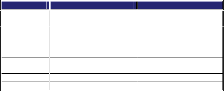
The following table lists the functions of the 6 dipswitches:
DIPSWITCH FUNCTION SETTING
1
Horizontal Position Control
On = Enabled*
Off = Disabled
2
Output Sync Format
(sync on green)
On = RGsB
Off = RGBS / RGBHV*
3
Output Sync Format
(RGBS or RGBHV)
On = RGBHV*
Off = RGBS
4
Monitor Emulation
at power up
On = Enabled*
Off = Disabled
5 Reserved
6 Reserved
* Factory Default Setting


