6
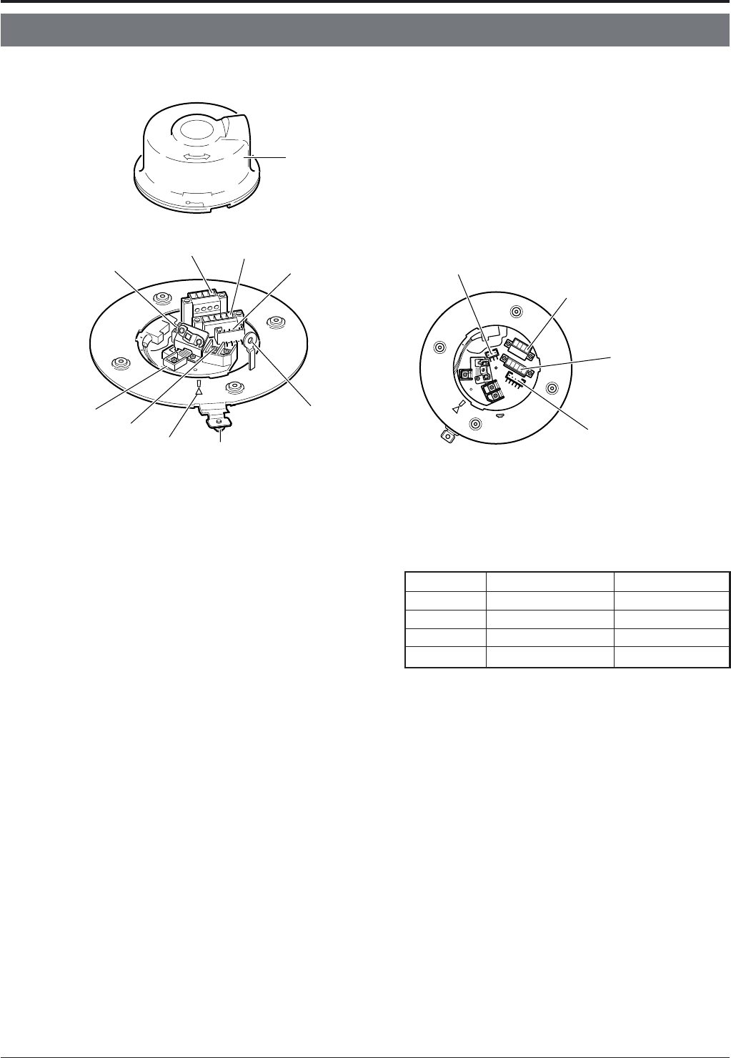
■ Camera body
1
[VIDEO OUT] Coaxial Cable Connectors
Output connector of a composite video signal (1 V(p-p))
with an output impedance of 75 Ω, to be connected to a
switcher, etc.
2
[AC ` 24V INPUT] Connector
Connect to a 24 V AC power supply.
3
Cover Position Alignment Mark
When attaching the cover, use this mark to align its final
position correctly.
4
Locking Screw
Tighten this screw to fasten the camera clamping bracket
*
.
5
Safety Wire Hole
To prevent the possibility of the entire camera falling down,
attach the safety wire between this hole and a secure at-
taching position in the ceiling.
6
Alarm Input Terminals (CN26)
This cannot be used.
7
[ALARM I/O] Input/output Terminals (CN23)
This cannot be used.
Introduction
Cover
(Connector side)
0
5
4
3
(Terminal Layout)
CONTROL terminal
(CN22)
8
7
9
6
8
7
6
2
1
9
Ⅵ Ceiling Mount
8
[CONTROL] Terminals (CN22)
Connect to a RM-P2580 remote control unit.
Controls, Connectors and Indicators
Pin No. Signal Name Mark
1 TX + A
⅜
2 TX – B
⅜
3 RX + C
⅜
4 RX – D
⅜
9
Alarm Output Terminals (CN24)
This cannot be used.
0
Cover
For protection against dust. Pierce the rubber cap on this
cover and pass the cable through the slits.
☞
P. 14


