3. MOUNTING AND WIRING
3
−
10
(c) Keep 24 VDC I/O wires separatlf wires from 100 VAC and 200 VAC wires.
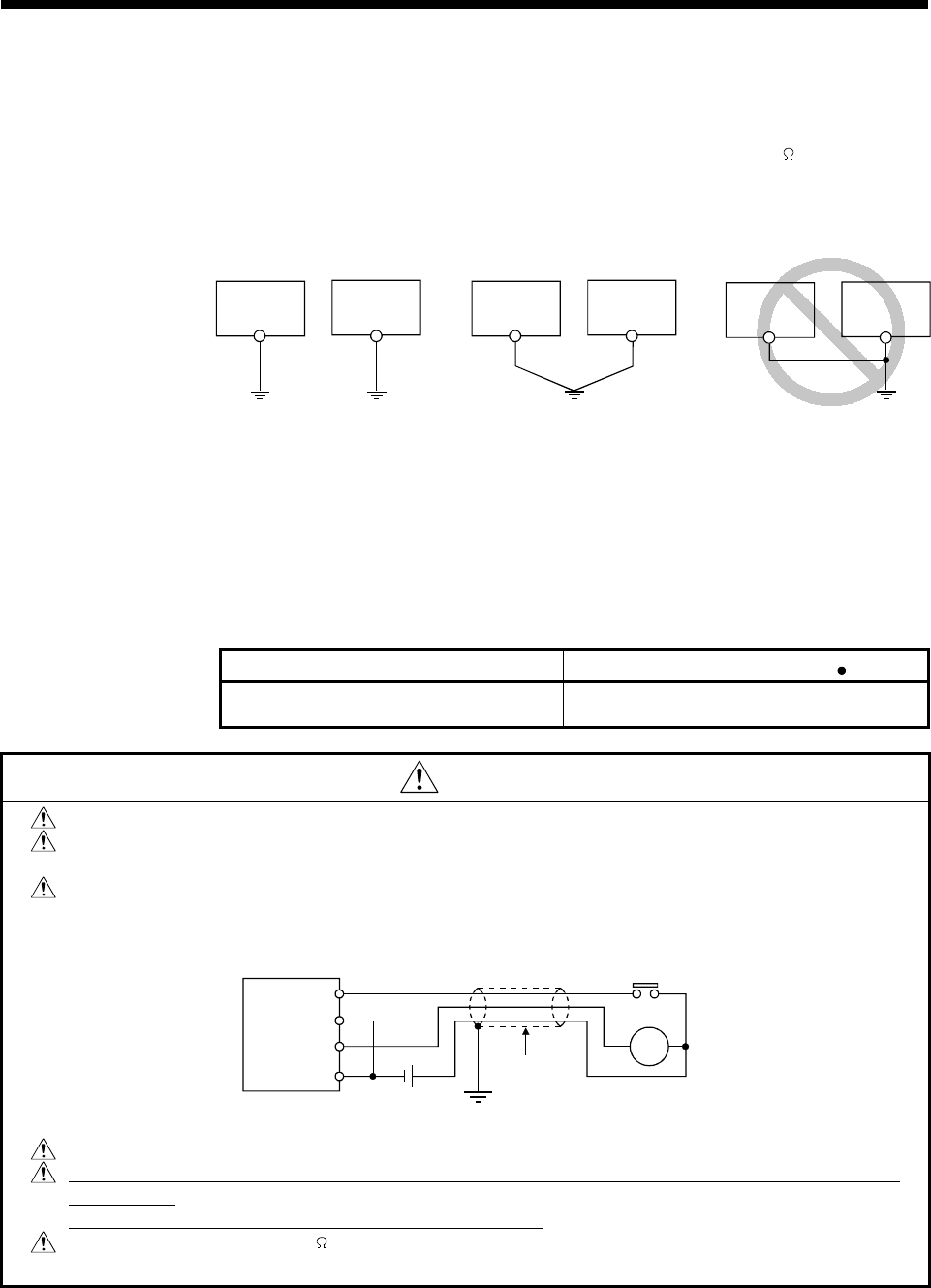
(5) Grounding
Connect the ground wiring as described in steps (a) to (c) below.
(a) Use a separate ground, if possible. Ground resistance 100
or less. (class
3 grounding)
(b) If a separate ground is not possible, connect to ground as shown in (2)
below.
Class 3 grounding
CPU module
Other
equipment
Class 3 grounding
Other
equipment
Other
equipment
(1) Separate ground connections
.......................... optimum
(2) Common ground connection
.......................... acceptable
(3) Common ground connection
...................... not permitted
CPU module
CPU module
(c) Grounding cables to be 2 mm
2
min.
Grounding point to be as close as possible to the
A173UHCPU/A172SHCPUN/A171SHCPUN and the distance to the
grounding point as short as possible.
(6) Module terminal block wiring screws
Tighten the wiring screws of the module terminal block within the following range.
Screw Tightening Torque Range N cm
Terminal block and terminal screws
(M3.5 screws)
59 to 88
CAUTION
Connect input and output wires along different routes.
Leave at least 200 mm (7.87 in) clearance between I/O wires and high-voltage, high-current
main-circuit cables.
If the I/O wires cannot be kept separate from the main-circuit or power cables, use shielded
cable for all of them and ground the shield at the CPU module end. However, if appropriate,
ground the other end of the shield
CPU module
Input
Output
DC
Shield
Shield cable
RA
Keep 24 VDC I/O wires separate from 100 VAC and 200 VAC wires.
The leakage current over long-distance wiring connections exceeding 200 m (656.17 ft.) can lead
to problems.
See Section 5.4.2 (9) for appropriate countermeasures.
Ground resistance to be 100 max (class 3 grounding). Do not share a common ground with
other equipment.
