Installation
3-14
Part 1061253B
E 2006 Nordson Corporation
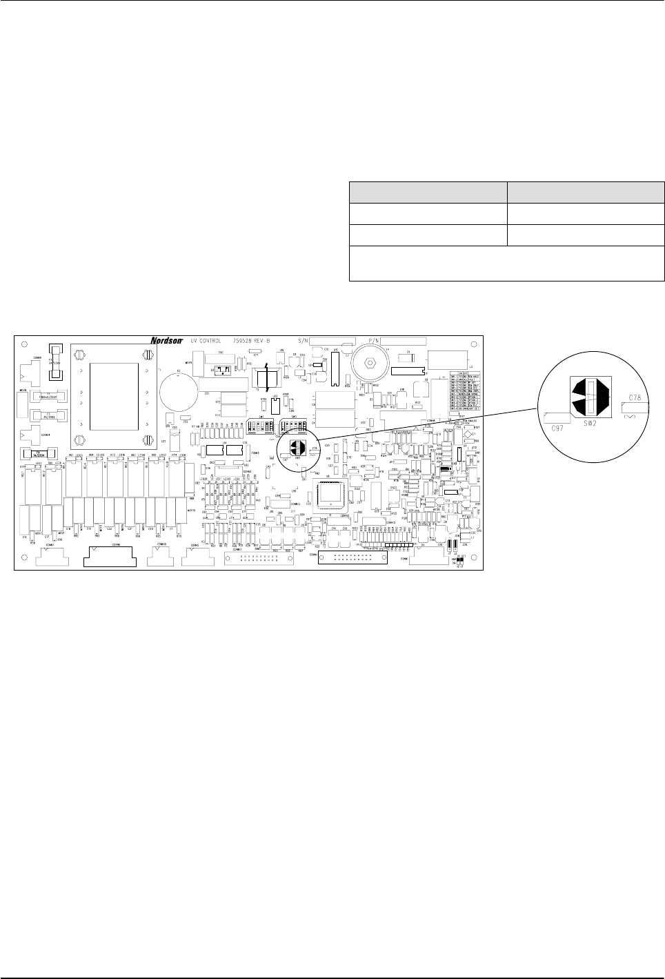
Power Supply Address Switch
See Figure 3-10.
The SW2 rotary address switch has positions 0
through 9 and A through F. The switch is used to
set the electronic address of the power supply if it
is part of a network.
When Remote Configuration (REM CFG) is
Enabled or ON on the control board, the address
must be set from the front panel.
When Remote Configuration (REM CFG) is
disabled or OFF on the control board, the address
must be set on the board.
Standalone Units
When operating the power supply as a standalone
unit (single) set the switch in the 0 position.
Networked Units
When operating the power supplies in a networked
configuration (master/remote), you must set the
rotary address switches as follows:
Unit Rotary Switch Setting
Master 0
Remote(s) any different value
Example: Set the master to 0, remote 1 to 1,
remote 2 to 2, etc.
1500118A
NORDSON
739034A
U6
0
71
9
10
12
3
4
6
OPEN OPEN
123456123456
0
Figure 3-10 Power Supply Address Switch on Main Control Board
Remote Configuration of
Main Control Board
Remote configuration allows for easy user interface
by using the front panel display and select buttons
to change the configuration settings of the main
control board. The main control board must have
SW1 and SW3 dipswitches in order for remote
configuration to be used.
To enable remote configuration:
S Set SW1-5 5 in the Closed/On position.
S If you are remotely controlling the output power
of the lamphead (used on variable output power
supplies only), set the jumper for 4-20ma or
0-10vdc now.
Configure the power supply (refer to Tables 3-14
and 3-15):
1. Connect input power to the power supply.
2. Place the front panel power switch to the ON
position. The system display will go through a
POWER UP TEST.


