5. - Entering the High Alarm Level Press the SELECT button again - the High Level Alarm Point
indicator LED on the graphic face and the top RED line in the bar graph display will flash.
P___P___
P___P___
P___ appears
in the display. Enter the level, using the INCREASE or DECREASE arrow to set the desired level. When
this point or level is reached, it will indicate a High Level Alarm has been reached and activate the control
circuit/device you have designed into your system.
6. - Entering the Sump ON Level Press the SELECT button again - the yellow Sump ON indicator
LED will flash along with the YELLOW line in the bar graph.
P___P___
P___P___
P___ appears in the display. Enter the
level, using the INCREASE or DECREASE arrow to set the desired Sump ON level. When this point or
level is reached, LVCN-302 will deactivate the differential output relay to the control circuit/
7. - Entering the Sump OFF Level Press the SELECT button again - the Sump OFF indicator LED
and the ORANGE line in the bar graph will flash.
P___P___
P___P___
P___ appears in the display. Enter the Sump OFF
level, using the INCREASE or DECREASE arrows. When this point or level is reached, LVCN-302 will
activate the differential output(s) to the control circuit/device you have designed into your system.
device you have designed into your system.
8. - Entering the Low Alarm Level Press the SELECT button again - the Low Level Alarm Point
indicator LED on the graphic face and the top RED line in the bar graph display will flash.
P___P___
P___P___
P___ appears
in the display. Enter the Low Alarm Level, using the INCREASE or DECREASE arrow. When this point or
level is reached, it will indicate a Low Level Alarm has been reached and activate the control circuit/device
you have designed into your system.
12. High Level N.C.
11. High Level Com
10. High Level N.O.
9. Sump ON N.C.
8. Sump ON Com
7. Sump ON N.O.
6. Low Level N.C.
5. Low Level Com
4. Low Level N.O.
3. Sump ON N.C.
2. Sump ON Com
1. Sump ON N.O.
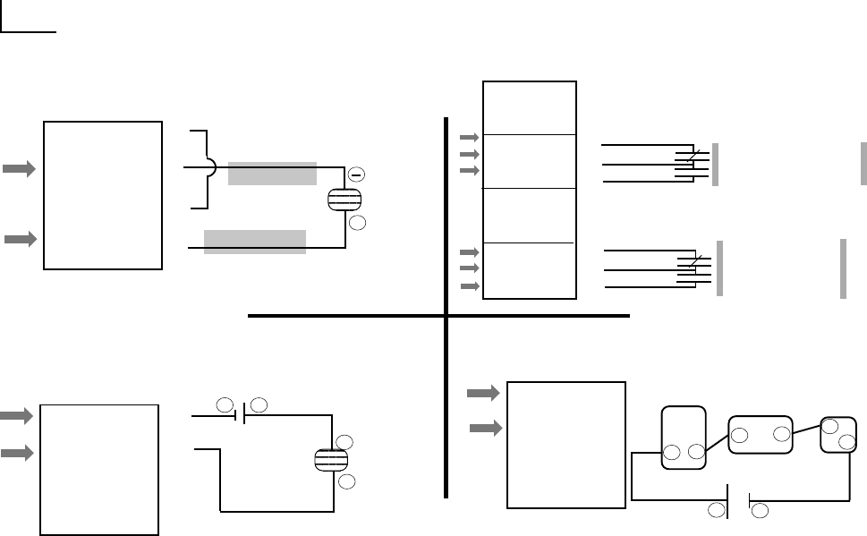
Signal Power Supplied by LVCN-302 (Loop Powered)
+24 VDC Output
Level Input
Transducer
Signal Power Supplied by Other Source
Sensor Input Connections / Schematics
Typical Form-C Relay Connection
Sending 4-20ma Signal to Other Devices
4. 4-20 mA (
-
)
3. 4-20 mA (
+
)
2. Ground
1. + 24 VDC Out
Sensor Input
Terminal
+
Level Input
Transducer
Sensor Input
Terminal
External
Power
Supply
+
Sensor Input
Terminal
LVCN-302
Sensor Input
3.
4.
+
Sensor Device
PLC
+
+
1.
(Transmitter)
4-20mA ( +)
3.
2.
4.
Jumper #4 to #2
4. 4-20 mA (
-
)
3. 4-20 mA (
+
)
2. Ground
1. + 24 VDC Out
4.
3.
-
-
+
(Transmitter)
+
4. 4-20 mA (
-
)
3. 4-20 mA (
+
)
2. Ground
1. + 24 VDC Out
-
-
-
-
Form - C
10.0 Amp @ 120 VAC
(noninductive)
Relay operates at
same level as #7-#9.
Consider it a spare
Form C sump relay.
9.
8.
7.
3.
2.
1.


